

+86 177 5198 6706
222, Block B, Diamond International, Guozhuang Road, Xuzhou, Jiangsu, China
The real scene inside and outside the space frame is part of an amusement park. The main body of the amusement park is a frame shear wall structure, and the roof is a steel space frame structure. There are many special-shaped structures.the highest point of the space frame main body (excluding the decorative fin part) is 46m, the lowest support elevation is 16.4m, and the support form adopts multi-point support on the lower string. The scale of the space frame is huge, the space is varied, and the span of the space frame is relatively large. The longest point from east to west is 117m, and the span reaches 99.5m; the farthest distance between the north and south ends is 275m, and the maximum span is 56m.
The real scene at the end of the space frame; b—the real scene in the middle of the space frame. Figure 1. The real scene of a certain engineering space frame. The quadrangular pyramids are being placed, and the space frame size of each section is 4m×4m. The large-span arched space frame bolt ball joint double-layer hyperboloid network structure, the structure becomes weaker from the middle to the surrounding. The space frame has been in use for nearly 6 years.
Due to some mistakes in the original design and construction, the design of the drainage system was seriously unreasonable, resulting in poor drainage on the roof and serious water accumulation, which caused additional loads. At the same time, the complex and huge main body of the network frame causes complicated stress on the rods, which requires stricter design and construction, especially in the high-altitude hanging cantilever areas on the east and west sides outside the support system, which are heavy and easily affected by external factors. Interference, such as poor welding quality of purlins in this area, a large area of roof panels falling off, causing the rods to directly contact rainwater and cause corrosion, and in the transition zone at the tail, the deformation of the rods is serious.

a—the real scene at the end of the space frame; b—the real scene at the middle of the space frame.
FIG. 1 Real scene of a space frame project
In short, the main defects of the space frame structure are as follows: space frame pipes are bent and deformed, some of them have a large amount of deformation, one rod is missing, many coatings are peeled off, and the rods are seriously corroded. See Figure 2. These are common space frames. Accurate statistics of these defects are crucial to the follow-up identification work.

a—space frame pipes are bent and deformed; b—Poor installation quality of space frame pipes;c—seriously corroded the space frame pipes
Figure 2 space frame defects
2 Calculation and Analysis
1) Load value. The load value of the structural bearing capacity checking calculation is determined according to the current GB50009-2012 “Code for Building Structure Loads” and related engineering drawings and materials: the dead load of the upper chord is 0.3kN/m2, the dead load of the lower chord is 0.05kN/m2, and the live load of the upper chord is 0.5kN/m2 , The constant load of the horse road is 1.5kN/m; the basic snow pressure is 0.4kN/m2, and the basic wind pressure is 0.55kN/m2.
2) Material strength and component size. The value of the material is determined according to the design strength of Q235 steel; the size and layout of the components are determined according to the engineering drawings.
3) Use SAP2000 to calculate the engineering space frame model. The main body of the space frame is shark-shaped. As shown in Figure 3, the space frame can be divided into 5 parts according to the layered space frame edges with the strip-shaped bulge in the middle, from the head (wide part) to the tail (thin tail). ) are Zone I, Zone II, Zone III, Zone IV, and Zone V respectively, of which Zones I to IV are located on the roof of the fourth floor nearly 30m above the ground, with drooping sides and uplifts in the middle. Area V extends from the fourth floor to the ground, and the end is supported by ground supports.
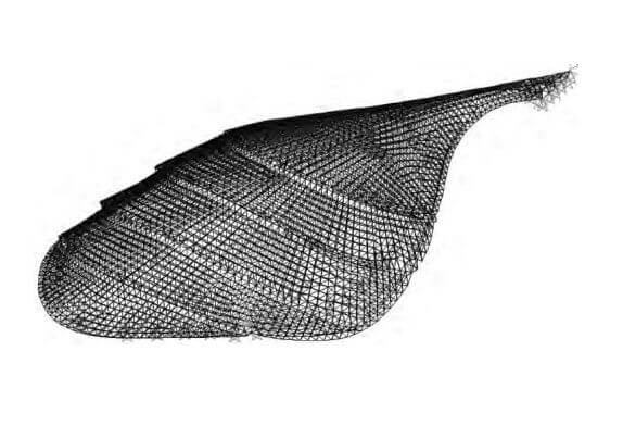
FIG. 3 SAP2000 calculation model of the space frame project
The checking results are as follows:
1) The bearing capacity of some upper chord members at the head and tail of the space frame is insufficient;
2) Part of the lower chord members in the middle of the space frame, the two wings, and the tail have the insufficient bearing capacity, and the insufficient bearing capacity in the two wing areas is more concentrated;
3) The bearing capacity of the web members of the space frame is insufficient, and the insufficient bearing capacity of the rear areas of the two wings is relatively concentrated;
4) The bearing capacity of the support members of the space frame is insufficient.
Figure 4 and Figure 5 are the calculation results of the whole space frame and the support rods respectively. Here, we don’t care about the specific values but only pay attention to the distribution interval of the rods with insufficient bearing capacity (the part marked with the coil in the figure). It can be seen from the figure that the bars with insufficient bearing capacity are distributed symmetrically, and most of them are along the edge of the support, or near the support, and the most serious area is V, especially near the end. And because this area is in the high-low transition zone, it is greatly affected by the environment, and there are a large number of corroded rods. After comparing many bent and deformed pressure rods on site, most of the positions are consistent with the calculated results, and a few are caused by improper construction and other reasons. Some tie rods also have the insufficient bearing capacity and need to be reinforced.

Figure 4 Calculation results of the overall bearing capacity of the space frame structure (stress ratio)

Figure 5 Calculation results of the bearing capacity of the space frame support members (stress ratio)
By comparing the actual defects of the space frame with the calculated bearing capacity results of the space frame, the quality of the space frame was evaluated, and it was determined that some bars of the space frame of the project were bent and deformed, and one web bar was missing: there was a connection between the bar and the spherical node The situation where the bolts are not fastened in place and the weld between the rod and the ball joint is disengaged; the coating of some rods and bolt balls falls off, the surface of the component is corroded, and the surface of a few rods is seriously corroded. At the same time, the bearing capacity of the space frame structure was checked and calculated. Some members of the upper chord, lower chord, web members, and support parts had insufficient bearing capacity, and most of the compression members were bent due to insufficient bearing capacity.
In view of the above identification conclusions, the processing opinions are given:
1) Replace or reinforce the bent, deformed, and missing space frame rods.
2) Tighten the unfastened joints between the rod and the ball joint, and repair or reinforce the part where the weld between the rod and the ball joint is disengaged.
3) Strengthen the rods with insufficient bearing capacity.
4) After the network frame is reinforced, the overall rust removal and anti-corrosion treatment are carried out to ensure the durability of the structure.
5) Redesign the drainage system and replace the existing drainage system and related substructures and decorative panels for the water accumulation problem that causes the space frame to be loaded for a long time.
Copyright © Xuzhou LF Engineering & Construction Co., Ltd. All Rights Reserved.

 +86-17751936871
 +86-516-8595-0258


