

+86 177 5193 6871
222, Block B, Diamond International, Guozhuang Road, Xuzhou, Jiangsu, China
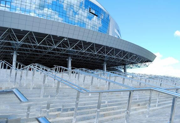
Figure.1 train station building
The total construction area of this project is 51489m², including a 15138m² station building and 32681m² platform canopy. The length of the station building is about 167m. The platform canopy is about 431m long. The station building is a frame structure, the roof is a steel space frame, and some are reinforced concrete roofs.
The space frame structure project consists of two areas: the entrance hall and the waiting hall. The bolt ball joints are placed in a square cone shape. The space frame structure of the entrance hall is about 3620m, and the space frame structure of the waiting hall is about 4105m, with a total of 7725m. The total amount of steel used for the space frame structure is 309.4t, and the support method is multi-point support around the upper chord and the lower chord cap. The space frame section height is 3.2m, and the variable section height is 1.4m. The space frame size is 3000×3500, the drainage slope is 5%, and the slope is found through the space frame structure itself and the supports. The space frame structure is overhanging around, 2.9m in the east and 7.9m in the north, west, and south. The space frame installation of this project adopts the scaffolding platform of the whole hall, and the installation method of hall and hall is carried out in sections. 1 Construction sequence.
According to the construction division, the construction sequence is as follows: Section 1 → Section I → Section II, as shown in Figure 2 for the section diagram.
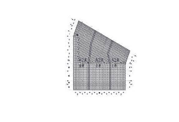
Figure.2 Sectional construction of space frame
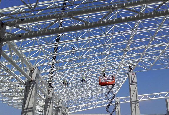
Figure.3 Space frame construction
The space frame adopts the high-altitude bulk method of a full steel pipe frame platform, and the platform is laid with frame boards at 19.500m and tied firmly with iron wires. After the construction of the space frame in Section 1 is completed, the installation of the waiting hall area in Section I will be carried out next. At this time, the components can be stacked in the vacant area of the 1-A~1-E axis and the 1-6~1-8 axis of the entrance hall. Before the space frame installations are initially formed, the components can be placed near the 2# tower crane for hoisting. In terms of the arrangement of the components entering the site, we will enter the site in 6~8 batches according to the needs of the installation sequence of the components, so as to ensure the needs of the installation progress and at the same time not cause a large number of components to accumulate. The construction sequence of the space frame project: space frame production → scaffolding erection → space frame installation→ space frame coating → roofing system.

Figure.4 Space frame lifting
According to the characteristics of the space truss project and the site construction conditions, the installation method of strips and sections is selected. According to the delivery list, check the accessories and installation drawings, check the various accessories, check the arrangement of the accessories, organize the loading and delivery of the accessories on the platform, and place them in an even and orderly manner, as far as possible according to the order of installation and the requirements for easy installation. Hook out the high-strength bolts in the bar with a special iron hook, assemble the corresponding sleeve and jacking wire, and check and verify the support and bolt ball.
In the actual installation process of the space frame, the process sequence starts from the axis (1-E), first place the support (1-E) and intersect (1-14) axis support ZZ3 as the starting point, and install the lower chord M27, M30 first, M39, M27 and ball 1204, four lower chords M27, M30, M27, M30, then install diagonal rods MB6, M39, M36, M39, and finally the upper chords M27, MBO, M30, M30 and upper chord balls 5053, 6048, 6038. Then proceed according to this method, the space frame is parallel to the lower string ball in the direction of the above-mentioned bearing.
Red brick pads need to be placed on the scaffolding board, and the scaffolding bears the downward load applied by the installed part of the space frame until it starts from axis B1 and is installed until axis B4 forms a rigid body. During this period, the scaffolding bears the maximum load is about 30kgm, the installed part of the space frame forms a rigid body, and all the loads are applied to the support (the scaffolding is not subject to the pressure of the space frame part, but only bears the pressure of the installer and equipment).
Before construction, retest the supporting surface (including the axis of the space frame on the supporting surface, the top of the column, the elevation, and the three-dimensional record of the supporting column) and keep the data on file after passing the retest. If the deviation exceeds the requirements, it should be reported to the on-site supervision engineer in written form for negotiation and handling, so as to do a good job in the operation of each process.
After the installation of each section of the space frame, the person in charge of the project arranges the second fixation in time, conducts a comprehensive inspection, and measures the length, width, and vector, so does not exceed the specification. If it exceeds the standard, the technical person in charge should immediately organize the construction team to make rectifications until it reaches the standard. And make an archive of the original record of installation. Notify and cooperate with the supervisor and the owner to carry out the acceptance before proceeding to the next step.
The temporary supporting brick pier used for assembly on the platform should ensure a certain strength to prevent uneven subsidence. During the assembly process, the axis offset and the vertical and horizontal length deviation should be checked frequently. The deviation should be controlled at 1/200 of the axis and not greater than 30mm. The allowable offset value is 1/3000 of the span and not greater than 30mm. The height deviation is 1/800 of the distance between adjacent supports and is not greater than 30mm, and the straightness of the bar axis is 1/100 and not greater than 1mm. The location, quantity, and height of the temporary fulcrums should be uniformly arranged, and the lower part of the fulcrum should be properly reinforced to prevent the fulcrum of the space frame from being overstressed locally and causing the shelf to sink. During the installation process of the space frame, the subsidence of each temporary fulcrum should be checked at any time. If there is a drop, it should be reinforced in time to prevent the phenomenon of falling. When dismantling the temporary fulcrum, it should be noted that several groups of fulcrums should be lowered synchronously. During the lowering process, the range of the lowering should not be too large. It should be gradually divided into stages and proportionately lowered, or the support should be removed with equal steps of no more than 100mm per step. point.
The construction of the next process cannot be carried out without inspection and acceptance. Each process is handed over for inspection and acceptance, and a record of acceptance is made.
For the anti-corrosion of space frame members colliding in the assembly process, it is necessary to carefully check and recoat, and there must be no missing coating, foaming, or falling. To achieve a one-time acceptance and achieve an excellent project, check the thickness after each layer of paint is painted. After all the paint is finished, 90% of the paint must reach the specified thickness value. If it is lower than the specified value, it must be repainted again. After the space frame structure is in place, carefully inspect the dimensions and deflection of each axis of the overall space frame structure. After the test results meet the requirements of relevant specifications, each support point can be fixed.
During the construction process of the space frame project of Xinyueyang Station on the Wuhan-Guangzhou Passenger Dedicated Line, the space frame has a large span and a large number of installation rods, so the connection of various processes must be done well. Before the space frame construction, the deformation of the structure should be understood through simulation analysis and calculation. During the construction process, measures such as pre-arching and pre-biasing are adopted to ensure that the spatial position of the structure is consistent with the design after installation. Select key points on the component as the measurement control points, combine the measured internal force and deformation data, analyze the stress and deformation of the structure in each construction stage under the conditions of sunshine and temperature changes, compare with the design prediction value, and find out the law. According to the mastered laws, corrective countermeasures are put forward to ensure that the internal force, shape, and spatial dimensions of the structure after completion are consistent with the design.
Copyright © Xuzhou LF Engineering & Construction Co., Ltd. All Rights Reserved.

 +86-17751936871
 +86-516-8595-0258


