+86 177 5193 6871
222, Block B, Diamond International, Guozhuang Road, Xuzhou, Jiangsu, China
For single-layer reticulated shell calculations, it is generally assumed (the nodes of a single-layer shell must be rigidly connected) that the nodes are rigidly connected. Single-layer reticulated shell is calculated according to the stiffened beam element, the rod in addition to bearing the axial force, also bears the bi-directional bending moment, shear force, and torque along the shell surface in the direction of the surface and the surface normal direction. Therefore, it is necessary to analyze the calculated lengths of reticulated shell members within the curved surface and in the direction normal to the curved surface respectively.
Calculated lengths of single-layer reticulated shell bars within the curved surface of the shell

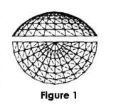
Figure 1 shows a common Schweder ribbed dome space frame shell. When welded hollow sphere nodes are used, the nodes can be considered to be rigid and the reticulated shell rod system constitutes a curved surface rigid frame. Currently, the lack of such a rigid frame for the test and Figure 1 research information, in the study of the rod in the curved surface of the calculated length, can be approximated as a general relatively flat reticulated shell, etc. Substitute for the planar rigid frame shown in Figure 2(a).

According to the dome reticulated shell force characteristics, the following assumptions can be made:
1) Neglect the slender diagonal rods on the ribs compression rods of the restraining effect;
2) Considering the role of annular rods “hoops”, that is after the generation of the planar stiffener is no lateral displacement;
3) The ribs compression rods in the reticulated shell at the same time lost stability.
In this way, the calculated length of the rib compression bar of the reticulated shell in the curved surface can be analyzed according to the sketch of the planar stiffener without lateral movement shown in Fig. 2(b). When the ring rod is subjected to tensile or axial force is zero, the ring rod has a certain restraining effect on the ribs compression bar through the node, in this case, the calculated length coefficient of the ribs compression bar μ¹≤1.0; when the ring rod is subjected to compression and destabilized at the same time with the ribs compression bar, there is no restraining effect on each other, and it can be taken that μ₉’=1.0. The calculated length coefficient of the compression bar in the curved surface of the reticulated shell obtained from the analysis above, μ₈’=1.0. ₈’value is of general significance.

For the cylindrical single-layer reticulated shell with a single diagonal rod system shown in Fig. 3, the calculated lengths of the ribs members in the curved surface can also be equated to the planar stiffener shown in Fig. 2(a) when analyzing the lengths of the ribs members in the curved surface. In this case, the restraining effect of slender diagonal rods can also be neglected, and the rib-oriented members are assumed to be unstable at the same time.
Since the single-shell silo generally requires strong bearing restraints at the ends as well, it can also be assumed that the stiffeners after equidistribution are free of lateral movement.
The calculated lengths of the rib compression rods of the single-layer shell in the curved surface can thus be determined concerning the computational sketch of the dome reticulated shell according to the planar stiffener without lateral movement shown in Fig. 2(b). Since the longitudinal bars of the single-layer mesh shell are generally weak, their restraining effect on the rib compression rods is small, and μg’=1.0 can be taken.
The force state of hyperbolic flat shells is intermediate between that of dome and cylinder shells and has similar properties to the above two.
For the saddle shell, since the rods are always in tension and always in compression, the tensile rods will strengthen the rotational constraints on the ends of the compression rods intersecting at the same node, which makes the computed length of the compression rods decrease compared with the reticulated shell of the above forms.
In summary, the calculated length factor of the single-layer reticulated shell compression bar within the shell surface can be biased to safely be taken as μs’ = 1.0.
