

+86 177 5198 6706
222, Block B, Diamond International, Guozhuang Road, Xuzhou, Jiangsu, China
The China-Laos Railway is an important project linking China’s Belt and Road Initiative with Laos’s strategy of turning a land-locked country into a land-linked country.
Biotin Station is an important part of the china-Laos Railway. It is the first railway station to enter Laos from China, with a construction area of 6,500 square meters and a design scale of 2 platforms and 4 tracks. (See Figure 1)
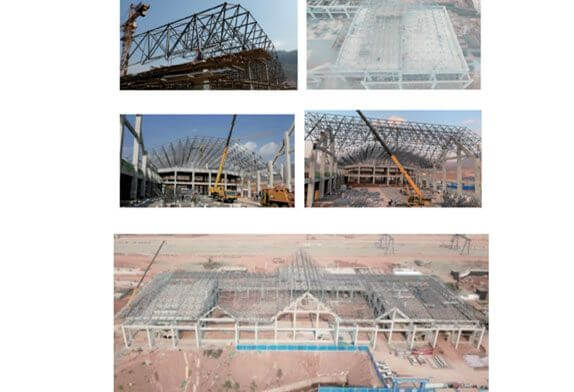
Figure 1 Boding Station Construction
The roof of the Moding station adopts a four-angle cone bolt ball steel space frame structure, with a total length of 145m and a width of 53m. There is a double slope spire in the middle, and two small spires are arranged on both sides of the front facade spire. The side facade adopts a double slope roof design, and the main specifications of the space frame rods are φ180×12, φ 159X12, φ140×4, φ 85.5×4, etc. The specifications of bolt balls are φ350, φ280, φ180, etc., and the specifications of bolts are M56, M39, M30, etc. The support of the network frame is the tensile spherical fixed hinge support. The layout of the bolt ball network frame in the Boding Station is shown in Figure 3. The space frame is distributed in the range of axis 1~17, wherein the main structure of axis 1~3 and 15~17 is 5.35m high, the structure of axis 3~5 and 14~15 is 10.5m high, the chord elevation of the space frame is 14.315m, and the height of the space frame is 3.3m
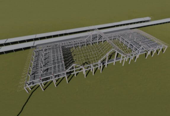
FIG. 2 Effect diagram of bolting ball space frame on the roof of Boding Station
Generally, the larger the span of the structure is, the larger its dead weight will be, reducing the structural dead weight is the necessary condition to realize the long-span structure, steel strength is high, the dead weight is light, and the bolted ball space frame structure is especially suitable for large space structure.
The commonly used methods of bolt-ball space frame mainly include a high-altitude scattered method, integral jacking or lifting method, and integral or block lifting method. Before the space frame construction, the outer axis 7-17 of the front facade of the Boding station house was a flood drainage channel 15m wide and 12m deep, and the back facade was a platform canopy. Construction equipment could not be parked on the back facade of the station house and the outer axis 6-17 of the front facade. The reinforced concrete construction of other main bodies of the station house had been completed before the space frame construction.
Both the overall construction method and the block lifting method need to occupy a large number of sites, and will not save the construction period when applied in this project. Considering the site environment factors, the high-altitude scattered construction method is more convenient and fast for this project, so the high-altitude scattered construction method is selected.
According to the characteristics of the project, the 14-15 axis site is small; 8~9 axis scaffold construction height is large and time-consuming; The top elevation of structures 1-3 and 15-17 is 5.35m, and the scaffold is about 9m high. The elevation of the concrete structure plate of axis 3-5 is 10.5m, and 4m scaffolding can meet the construction demand, with the minimum amount of scaffolding required. Cranes can be parked in all four directions. The construction site has enough materials to spread and store, and there are enough places for assembling small assembling units. 3~5 axis assembling after completion of 3~1 axis and 5~17 axis space frame. (See Figure 3)
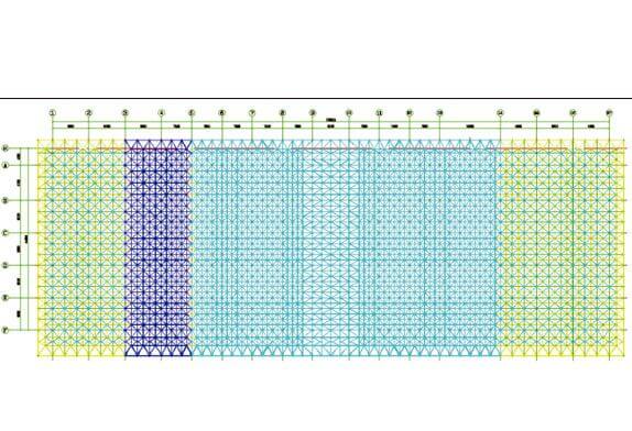
Figure 3 Boding Station space frame layout
Usually, the design unit of the analysis of the structure is after the establishment of the overall structure model, at the same time to apply the load to carry out. But in fact, the construction is carried out in sections, and even the same part will have different construction sequences and loading conditions. The difference between the structural system under construction conditions and the original design state will lead to the difference between the original design analysis result and the actual structural effect during construction. When the structural system changes with the progress of the project, the internal force of the component is in the stage of dynamic adjustment, and its maximum deformation and stress may occur in the construction stage. Therefore, in order to predict the deformation and stress changes in the construction stage, it is very necessary to analyze the construction stage. This case uses finite element software MIDAS to simulate and analyze the whole construction process of the steel structure. The structure is installed with temporary support, the top of the temporary support is supported on the lower string ball of the space frame, and the temporary support is arranged in position. (As shown in FIG. 4) In the calculation model, the temporary support position adopts a hinged constraint. (See Figure 4).
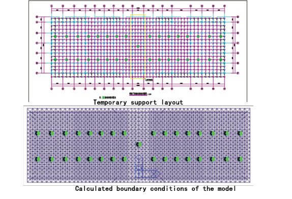
FIG. 4 Temporary support layout and Calculated boundary conditions of the model
3.1 Selection of construction conditions
According to the construction process, the most representative construction stage is selected for calculation, and two installation and construction working conditions cs1 and CS2 are selected respectively. The working conditions are as shown in FIG. 5
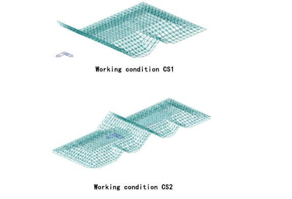
FIG. 5 Working condition CS1-CS2 (working condition of space frame construction halfway)
3.2 Calculation results of construction conditions
(1) Structural deformation (as shown in FIG. 6).
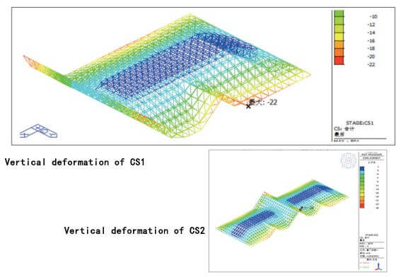
FIG. 6 Vertical deformation of CS1-C S2 in working condition (mm)
After the scheme is determined, REVIT software is used for modeling to simulate the construction scheme and process and determine the reasonable construction sequence and small unit specifications during lifting. After that, flow simulation is used to coordinate the scheme disclosure and safety and technical disclosure to simulate the construction process. (As shown in Chart 1)
The space frame of this project is a bolt-ball space frame, and the construction process is determined as follows: scaffold installation → installation of A/3~5 axis support → installation of 2 to 4 rods and A bolt ball to form A small assembly unit → installation of 3~5 axis space frame from axis A to axis F → installation of 3~1 axis space rame → installation of 5~17 axis space frame, site installation process.
BIM technology is used to carry out in-depth design and construction process demonstration of the bolt-ball space frame of the China-Laos Railway Moding station. The installation method of high-altitude scattered space frame is adopted, which well overcomes the problems of narrow sites and limited large-scale equipment. It is a very successful high-altitude scattered network frame case, which provides reference and experience for other similar engineering construction. According to the characteristics of the project and the environment, selecting the most suitable construction method, can effectively control the construction cost, ensure that there are no safety and quality accidents in the construction process, and create good social benefits.
|
Process 1:3 ~5-axis scaffolding is completed, temporary fixed support is completed, and the first quadonal cone is hoisted. |
Process 2: Lift the adjacent half of the short span quadcore (lift the red part at the same time after assembling and forming the ground). |
Process 3: Form a second tetragonal cone system. |
Process 4: Lift half a tetra at a time |
|
Flow 5: Install 3~5 axis overhanging range bolt ball frame. |
Flow 6: High altitude scattered installation from 3 axes to 1 axis。 |
Flow 7: High altitude scattered installation from axis 5 to 17. |
Flow 8: The installation of the space frame of Boding station is completed. |
Copyright © Xuzhou LF Engineering & Construction Co., Ltd. All Rights Reserved.

 +86-17751936871
 +86-516-8595-0258


