

+86 177 5193 6871
222, Block B, Diamond International, Guozhuang Road, Xuzhou, Jiangsu, China
In order to change the impression of the waste power generation industry in people’s minds and eliminate psychological resistance, the waste incineration power plant pays special attention to deindustrialization construction and strives to build a garden power plant. The structural design features of high clearance and a large span of waste incineration power station make steel space frame gradually replace the traditional reinforced concrete structure and become the mainstream design of closed main workshop in the waste incineration power generation industry. The waste incineration power generation project is the people’s livelihood security, environmental protection, energy conservation, and emission reduction is an important municipal utility infrastructure, is to realize waste reduction, recycling, and harmless environmental protection engineering, social awareness is high, the rack construction occupies a larger proportion of construction in waste incineration power generation engineering, safety quality and efficient combination of space truss hoisting task is of great significance.
1 Project Overview
The eastern Environmental protection Energy Project is the largest garbage incineration power generation warehouse project in central China, which will be built into a garden-style environmental protection industry demonstration project. The main functional areas of the waste incineration power plant are divided into an unloading hall, garbage pool, incineration room, flue gas purification room, and garbage transportation ramp, which are arranged symmetrically in the north and south. In order to realize the characteristics of the garden style, several functional areas adopt fully enclosed designs. The main structure adopts a reinforced concrete structure + space frame structure, in which the unloading hall and garbage pond area are mainly reinforced concrete structure + space frame structure, the burning room, and flue gas purification room are the main steel structure, and the steel structure is divided into four limbs lattice column support system and space frame roof structure. Square pyramid grids are all used. The roof is divided into five areas, which are located in the unloading hall, garbage pond, incineration room, flue gas purification room and fly ash solidification room. The layout is symmetrical in the north and south, and the structural form, size and cross-section are identical (see Figure 1).
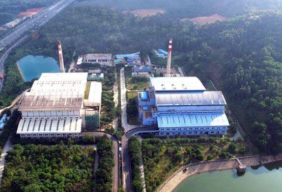
Figure 1 space frame roof layout of the eastern environmental protection energy project
2 Construction technology of space frame roof in waste incineration power plant
2.1 Unloading hall space frame construction
The discharging hall adopts the square pyramid space frame, the node adopts the bolt ball node, the welded hollow ball node is used locally, and the string support is adopted. There are 38 bearings in total, and the bearings are arranged symmetrically. The size of the space frame is 100m×32m. The distance between the long side bearings is 10m, 7m, and 6m, a total of 32, and the gable walls at both ends are 3, and the distance between the bearings is 8m. The installation height of the network frame in the unloading room is not high. The unloading platform is directly below the network frame, and the site is flat. The ramp can be used to enter the truck crane, which is assembled and hoisted in blocks on the floor. The network frame in the unloading room is divided into 11 units, the heaviest of which is 10.46T. After assembling, a 75T truck crane is used for hoisting, and the assembling direction is from east to west (see Figure 2).
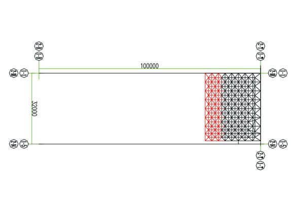
FIG. 2 Assembling direction of space frame in unloading hall
2.1.2 Unloading hall space frame construction process
Firstly, the first piece of the space frame is assembled on the unloading platform, and then the first piece of the space frame is lifted by an automobile crane. Refer to the above steps to assemble the second space frame, lift the second space frame with a car crane, and complete the subsequent lifting work of the subsequent space frame unit (see Figure 3).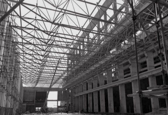
FIG. 3 Space frame construction of unloading hall
2.2 Construction of garbage tank space frame
The size of the space frame is 100m×35m. The distance between the long side supports is 10m, 7m and 6m respectively, a total of 32. There are 3 gables at both ends, and the distance between supports is 9m and 8m.
2.2.1 Construction idea of garbage tank space frame
Due to the particularity of the location of the garbage pond, it is difficult to cover the grid lifting machinery arranged on both sides of the garbage pond, so the garbage crane in the garbage pond can be used as the horizontal transportation tool of the space frame.
In order to reduce transportation distance and improve construction efficiency, the installation site of the garbage tank space frame is arranged between the south ramp and the garbage tank, and the installation site and mechanical station of the garbage tank in the north and south areas are arranged symmetrically.
Rubbish rack for welding net, twelve blocks when on the ground, complete the north and the south area adopt 250 t crawler crane for lifting equipment, in the car set-up support frame, lacing good ground grids to the supporting frame, and then each block network frame design of cranes to the specified location, until the space truss hoisting.
2.2.2 Sliding construction process of garbage pond space frame
The first piece of network frame is assembled on the ground, and the first block unit is placed on the support frame of the vehicle by using a 250T crawler crane, and the vehicle is pulled by an electric hoist until it reaches the design position. After the network frame is fixed, the vehicle is moved to the other side, and the second piece of the network frame is assembled and hoisted onto the vehicle. Similarly, the remaining grid units were slid to the designed position by means of the crane. Finally, the crawler crane was used to lift the last space frame unit into position to complete the hoisting work of the entire garbage pond space frame (see Figure 4).
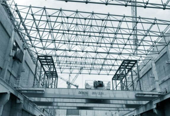
FIG. 4 Slippage of garbage pond space frame
For different projects, according to the span of the garbage pond and lifting machinery, the construction method of direct lifting and placement by fragment combination can also be adopted.
2.3 Space frame construction in the incineration room
There are a total of 12 supports in the incineration space, and the supports are arranged asymmetrically. The size of the network is 95.05m×43.6m. There are 11 long-side supports, and one gable at both ends. The block hoisting method is adopted for the network frame in the incineration room. After the network frame block is assembled on the ground, a 500T crawler crane is used to lift the network frame block to the established position, and then the upper air rod is added at the junction of the network frame block, and finally, the positioning is adjusted.
Due to the uneven distribution of lattice columns between incineration and the large column distance, the maximum is about 30m, resulting in a large distance between space frame supports. In order to prevent the fragmentation of the space frame unit from bending down too much deformation, to ensure that the space frame unit high altitude smooth rod is repair, it is necessary to set temporary support below the space frame.
2.4 Space frame construction of flue gas purification room
There are 18 bearings in the flue gas purification room, and the bearings are arranged asymmetrically. The size of the frame is 77.05m×55.7m. There are 12 long-side bearings, and 3 gable walls at both ends.
2.4.1 Space frame construction scheme of flue gas purification room
The eastern environmental protection energy project incineration plant adopts three incineration lines from the north to the south in a symmetrical arrangement. The whole core power area is arranged in a “return” type, and the chimney is arranged in the middle. In order to ensure the overall construction progress of the chimney, construction channels should be reserved for the chimney. According to the characteristics of force arrangement and the order of equipment arrival, the chimney feeding channel is reserved in the north flue gas purification area. This makes the construction of the flue gas purification room in the north and south areas adopt two sets of schemes. 2.4.2 Grid construction process of flue gas purification room
500T crawler crane was used to lift the network frame of the flue gas purification room in the south area, and the network frame unit of the incineration room was alternately lifted (see Figure 5).
FIG. 5 Cross lifting of flue gas purification room and incineration room in south Area
In the north area, the flue gas purification room adopts block hoisting to start and add high-altitude bulk. The first span starter frame is assembled in the first unit of the flue gas purification room, followed by high-altitude bulk.
Limited by site conditions, there is no large crane station on site. In order to ensure the smooth mending rod of the grid unit at a high altitudes, temporary supports should be set at the lower part of the starting span of the east and west grids. The west starting span is divided into four sections and hoisted in place by a 250T crawler crane, while the east starting span is divided into two sections and hoisted in place by 220T automobile crane. See Figure 6 for support layout.
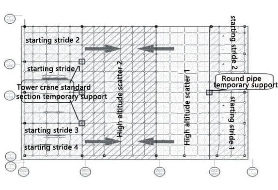
FIG. 6 Flow chart of grid assembly of flue gas purification room in South Area
The first span network frame in the east was assembled on the ground and then lifted to the design position in two sections by a 220T truck crane. Then, on the basis of the initial span network frame, the network frame was scattered in the air and installed in one piece. After the completion of one piece of aerial assembling, the first span network frame in the west is assembled on the ground and hoisted into four sections to the design position by a 250T crawler crane. Based on the west starting piece and the high altitude scattered piecing 1 piece, from both sides to the middle of the high altitude scattered piecing to complete the overall grid combination installation work. In the process of assembling and hoisting, the structural stress is different from that in the design stage. On the one hand, boundary support conditions and structural stress systems may be different. On the other hand, the whole structural system is a process of gradual establishment, there is structural transformation, and part of the rod stress characteristics may change, so it is necessary to calculate several key working conditions in the construction process, the possible adverse factors for early warning, in order to ensure the safety of structural construction.
Copyright © Xuzhou LF Engineering & Construction Co., Ltd. All Rights Reserved.

 +86-17751936871
 +86-516-8595-0258


