

+86 177 5193 6871
222, Block B, Diamond International, Guozhuang Road, Xuzhou, Jiangsu, China
The steel space frame structure has the advantages of small space force, light weight, high rigidity and good seismic performance, and is widely used in the roof of public buildings such as gymnasiums, theaters, and exhibition halls. The disadvantage is that there are many rods at the nodes, the installation technology and accuracy are required to be high, the steel members are easy to corrode, and the fire resistance is poor, requiring regular inspection and maintenance. After the steel space frame has been put into use for a certain period of time, corrosion and other phenomena often occur, resulting in a decrease in its durability and a certain safety hazard. Therefore, it is necessary to carry out a safety appraisal on the existing steel space frame structure that has been used for a certain number of years.
1Project overview
The main body of ais designed as a 5-story frame structure, and the roof is a circular dome space frame structure. Its appearance is shown in Figure 1. The seismic grade of the project is grade 3, the seismic fortification intensity is 6 degrees, the design basic seismic acceleration is 0.05 g, and the design service life is 50 years. The project was completed in 2003 and has been in use for more than 15 years. In order to understand the current status of the space frame structure, Huaibei Sports Center entrusted Jiangsu Construction Engineering Quality Inspection Center Co., Ltd. to conduct a safety appraisal of the space frame roof of the project.
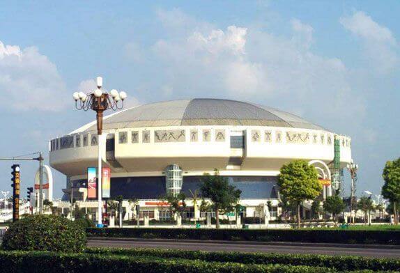
FIG. 1 Appearance of Huaibei Gymnasium
2 Structural layout inspection and data verification
2.1 Structural layout inspection After on-site inspection, the projected area of the space frame of the project is about 5000 m2, the fulcrum is in the form of peripheral point support, the elevation of the fulcrum is 23.84 m, and the elevation of the dome is 35.84 m. The spans of the fulcrum along the center line of the space frame are 70 m, 72.4 m, and 74 m respectively, and the space frame is extended out of the fulcrum with a cantilever of about 5 m. The entire space frame is connected to a ring-shaped steel beam with a diameter of 70 m through 64 supporting points, the steel beam and the 32 column tops are connected by rubber bearings, and the space frame nodes are bolt ball nodes. Compared with the design drawings, the space frame structure layout of the project is consistent with the design, the structure layout is reasonable, and the force transmission path is clear. The schematic diagram of the spatial layout of the space frame structure is shown in Figure 2, and the cross-sectional view of the space frame is shown in Figure 2.
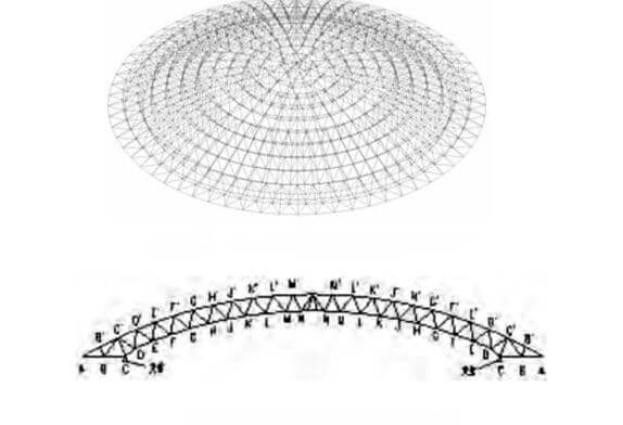
FIG.2 Space frame layout
2.2 Data verification
Checked the relevant test reports on Huaibei Gymnasium roof provided by the entrusting party. A total of 31 test reports of steel raw materials for space frame frames were checked, of which 8 were steel structure trusses, 6 were steel truss webs, and 15 were steel trusses. For the truss chords, two are the lower struts, and the steel space frame structure uses three types of steel: Q235B, Q355B, and 20# steel. All inspection reports are qualified. An overall steel structure inspection report was also checked and found to be acceptable.
3 On-site inspection
3.1 Section size detection of space frame structural members
The ultrasonic thickness gauge measures thickness according to the principle of ultrasonic pulse reflection. When the ultrasonic pulse emitted by the probe passes through the object to be measured and reaches the interface of the material, the pulse is reflected back to the probe. The thickness of the material being measured. In this appraisal project, the ultrasonic thickness gauge is used to detect the cross-sectional dimensions of the structural members and steel ring beams of the space frame. Before the test, remove the paint layer, oxide scale, rust, etc. on the surface of the structural member, and polish to reveal the metallic luster. Then apply the couplant to the place to be measured, couple the probe to the component to be measured, and then measure, and keep the contact coupling time for 1s~2s. Rotate the probe through 90° at the same position and make a second measurement, and take the average value of the two times as the representative value of the part. When measuring the wall thickness of the pipe, make the sound insulation layer in the middle of the probe parallel to the axis of the pipe. A total of 46 space frame members were extracted on site, and their diameters and wall thicknesses were measured. It was confirmed that the cross-sectional dimensions of the space frame members basically met the design requirements. The section size of the steel ring beam is measured, and it is confirmed that the section size of the steel ring beam basically meets the design requirements.
3.2 Deformation detection of space frame structure
The total station is used to test the deformation of the space frame structure, and the bolt ball joints at the part of the outer overhang are extracted at the site, and the ball joint at the bearing is used as the base point to measure the height difference with the corresponding base point, and the measured value and the theoretical height difference Compared with the height difference under the envelope condition calculated by the model, the measured height difference is between the theoretical height difference and the height difference under the envelope condition calculated by the model. Extract part of the upper chord nodes of the axis, measure the elevation of the upper chord nodes one by one from the outside to the inside with the outermost spherical node as the base point, and use the support as the reference point to calculate the deformation value of each node and compare it with the deformation value under the envelope condition calculated by the model. After testing, the measured deformation is smaller
3.3 Inspection of rubber bearing of space frame structure
A general survey was carried out on the rubber bearings of the space frame structure, and it was found that the rubber of some bearings was partially detached, the limit plates of some bearings were tightly attached, and no obvious aging phenomenon of the rubber was found. then the deformation under the model calculation envelope condition.
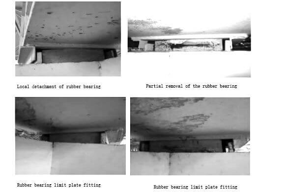
FIG.3 Inspection of rubber bearing of space frame structure
3.4 Detection of coating thickness of space frame structure members
The paint film thickness gauge uses the method of magnetic sensing thickness to measure the thickness of the non-magnetic coating on the magnetic conductive material. When the probe of the paint film thickness gauge is in contact with the coating, the probe will form a closed magnetic circuit with the magnetic metal substrate, but the non-magnetic coating on the surface of the magnetic metal will block the magnetic circuit, resulting in a change in magnetoresistance. The amount of change in magnetoresistance, the thickness of the surface covering layer can be obtained. During the on-site inspection of the coating thickness of the pole members of the space frame structure, 5 locations were inspected on the same component, and each location was inspected at 3 measuring points with a distance of 50 mm. The coating at the selected measuring point has good adhesion to the steel, and the distance from the edge or inner corner of the component is less than 20 mm. A total of 46 space frame components were extracted on site, and the total thickness of the dry paint film on the surface of the components was tested. The total thickness of the dry paint film of the coating should be 125μm indoors, and its allowable deviation is -25μm. After testing, the measured paint film thickness of the components meets the requirements of the relevant specifications.
3.5 Internal quality inspection of space frame welds
The factory splicing and butt welds of the engineering mesh components are all first-class welds, and other butt welds are second-class welds. After data verification, the test results of the steel structure weld flaw detection report are all qualified; some steel member welds were extracted on site for ultrasonic flaw detection, no excess defects were found in the tested welds, and the internal quality of the welds reached the “Steel Structure Engineering”. Construction Quality Acceptance Specification “GB50205-2001”.
3.6 Enclosure damage and space frame structure roof damage detection
The infrared thermal imager uses infrared detectors and optical imaging objective lenses to receive the infrared radiation energy distribution pattern of the measured target and reflect it on the photosensitive element of the infrared detector. The detector converts the infrared radiation energy into electrical signals, which are amplified and converted. Or a standard video signal displays an infrared thermal image through a TV screen or monitor and establishes a correlation between radiation and surface temperature. This thermal image corresponds to the thermal distribution field on the surface of the object, and the different colors on the thermal image represent the different temperatures of the measured object. By viewing the thermal image, you can observe the overall temperature distribution of the measured target, study the heating of the target, and then judge the next step. For structural damage, the heat capacity of the damaged part and the normal part is inconsistent. In the process of changing the ambient temperature, the temperature of the damaged part and the normal part will be different, so although the color of the surface is the same, the temperature difference can be seen in the thermal imager clearly reflected. After inspection by the infrared thermal imager, no obvious damage defects were found on the outer protective structure and roof of the project.
3.7 Structural damage and defect inspection of space frame
The damage and defects of the structural members of the space frame structure of the project were inspected, and a few rods had local paint film peeling off, and some rods had the paint film aging. The results are shown in FIG.4
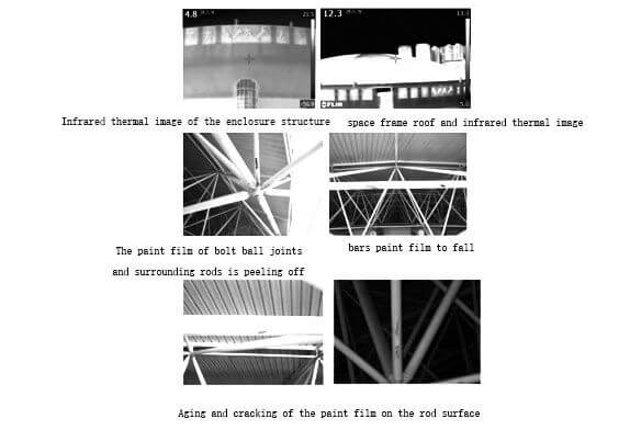
FIG.4 space frame structure
According to the results of on-site inspection and testing, the reliability appraisal and rating of the cover unit of the steel space frame roof is as follows: the space frame structure layout of the project is consistent with the design; the cross-sectional dimensions of the steel structure members are basically in line with the design requirements; The deformation is smaller than the deformation under the enveloping condition of the model calculation; the thickness of the paint film of the steel structure is in accordance with the specification requirements; the internal quality of the welded joints of the space frame structure is in accordance with the specification requirements; after calculation, the strength-stress ratio of the space frame structure members is less than 1.0, and the bearing capacity is It meets the requirements for use; the out-of-plane stress ratio or in-plane stress ratio of some rods is slightly larger than 1.0, and the slenderness ratio of the rods meets the requirements. According to the national standard of the People’s Republic of China “Civil Building Reliability Appraisal Standards” GB50292-2015, the safety rating of the upper space frame structure of the project is rated as Bu, and the normal usability rating is Bs, so the reliability rating is B. The suggestions for the continued use of the space frame roof of this project are as follows:
(1) Derusting and repainting the space frame rods with rust marks. (2) Release the tight rubber bearing limit plate. (3) Without technical appraisal or design permission, the layout, purpose and use environment of the structure shall not be changed, and the use load shall not be greater than the design and check load. (4) Regularly inspect and maintain the main force-bearing components every year. If any problems are found, a qualified testing agency should promptly inspect and identify its structural safety, and a qualified design and construction unit should be invited to carry out corresponding technical treatment.
Copyright © Xuzhou LF Engineering & Construction Co., Ltd. All Rights Reserved.

 +86-17751936871
 +86-516-8595-0258


