

+86 177 5198 6706
222, Block B, Diamond International, Guozhuang Road, Xuzhou, Jiangsu, China
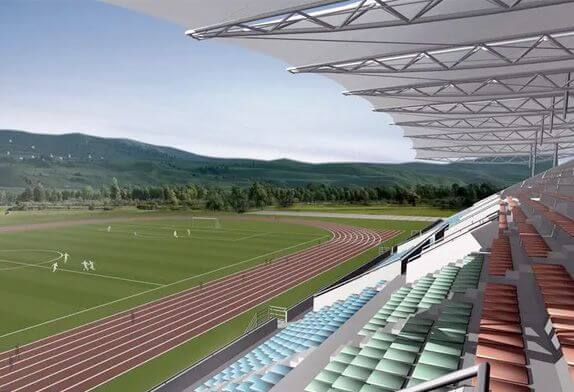
1. Stadium Stand Project Overview
Hohai University Stadium Stand is a three-story frame structure with a construction area of about 5,000 square meters. Its canopy adopts a skeleton tensioned membrane structure, with a projected area of about 1 500 square meters and total steel consumption of about 34t. The end-pull cable, the flying column, and the membrane body constitute a spatial cable-membrane structure system, which can be divided into 9 unit membranes, and each unit membrane is unimodal. According to the structural arrangement of the stands, the front cantilever length of the main truss has five specifications of 14~16m, the rear cantilever length is 3.75m, the span between columns is 8m, the lowest point of the column top is 21m, the highest point is 23.45m, and the side layers are obvious. , The overall shape is simple and lively.
2. Stadium Stand Overall Analysis
The membrane structure canopy is composed of 9 membrane units, each membrane unit is supported on the outer ring concrete frame column through the steel column, the membrane unit is connected into a whole by splicing at the notochord, and finally, pretension is applied in groups to keep the whole system always Under the tension state required by the design. Each steel column supports a membrane unit, and through the cooperative work of steel trusses, steel columns, flying columns, and notochords, the membrane body is stretched and the force is transmitted to the lower reinforced concrete stand.
In the system, only the lower end of the steel column and the rear end of the truss is fixed on the outer ring concrete frame column and the outer ring beam at the rear of the stand, and other members are rarely related to the lower concrete. Therefore, the force transmission line is clear and the concrete frame The column basically bears the pressure, and the entire concrete frame system bears the sheer force from the upper part, which fully exerts the overall bearing capacity of the concrete frame.
The drainage of the entire membrane surface adopts a combination of organized drainage and free drainage. For the rainwater between the two membranes, the drainage channel set at the upper part of the truss and the drainage pipe set at the rear of the truss can be connected with the drainage of the main structure. The systems are connected to form organized drainage. The rainwater on the front and rear sides of the membrane body is discharged to the outdoors through the free edges of the front and rear along the membrane surface.
The tensioned membrane structure has been widely used for its light structure and beautiful shape. Due to the particularity of the structure, its calculation theory and design method are quite different from those of conventional rigid structures. From form-finding analysis, load analysis to cutting analysis, the expression of geometric shapes runs through the whole process of membrane structure design.
Copyright © Xuzhou LF Engineering & Construction Co., Ltd. All Rights Reserved.

 +86-17751936871
 +86-516-8595-0258


