

+86 177 5193 6871
222, Block B, Diamond International, Guozhuang Road, Xuzhou, Jiangsu, China
1、Project Overview
The final assembly workshop of the space frame project is 421.6m long and 189.4m wide. The whole workshop is divided into 10 units by four transverse expansion joints and one longitudinal expansion joint. According to the requirements of the production process, the plane size of the column mesh is set at 21.0mX12.0m, and its plan is shown in Figure 1. The elevation of the column top of the workshop is +7.80m, and the insertion distance between the expansion joints and shrinkage axes is 400mm.
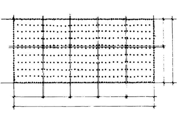
FIG. 1 Plan of golf assembly workshop
The first phase of the plant is used to produce 150,000 cars a year, and the second phase of the plant will be built 10,000 m2 to the west, which will produce 300,000 cars a year. The total assembly production line in this workshop is more than 10 kilometers long. Many types of equipment and the push rod catenary used to transport car parts on the production line are suspended under the roof load-bearing system, and the hanging load under the roof is large. In addition, with the change in the production process and production program, the action size and action position of the suspended load on the lower part of the roof will also change accordingly. Therefore, although not all parts have hanging loads in the current production, the technical requirements provided by German Volkswagen are that the roofs of all parts of the entire workshop are designed according to the hanging load of 2.5kN/m2; in addition, 0.5kN/m2 needs to be considered Utility line suspended loads. The whole plant is fully enclosed, using mechanical ventilation and artificial lighting. A large number of ventilation equipment are installed in the two ventilation rooms above the roof, each with a width of 10.5m, a length of 420m, and a height of 5.0m, which means that the roof system will bear the load of many ventilation equipments. Since the part below the lower chord of the roof system will be equipped with mechanized suspension equipment, a large number of public pipelines will pass inside the roof, and a large space must be reserved inside the roof to ensure the vertical and horizontal layout of public pipelines, especially if the diameter exceeds 1.2m ventilation pipe.
2、Structure selection
The golf assembly workshop has a large plant area and heavy suspension loads. The plant structure must meet the requirements of the production process and must also have good seismic performance. The plan of plane truss plus 12.0m steel bracket and large roof slab was initially considered, but it was rejected due to its poor spatial rigidity, heavy roof and poor seismic performance. After comparison, it is decided to choose the steel space frame with strong bearing capacity and good seismic performance as the roof bearing structure. Taking into account factors such as price and self-weight, it was decided to use GRC panels as roof panels.
The positive quadrangular pyramid space frame is widely used in the multi-point support continuous space frame in industrial plants, but its web rods occupy space, cannot meet the requirements for setting ventilation ducts, and the number of rods is large, so it was abandoned. In order to ensure the setting of the ventilation pipes, it is feasible to use the orthogonal truss. For the 21.0mX12.0m column space frame, a 3.5mX3.0m space frame is used, as shown in Figure 2, but this scheme is not ideal due to many nodes and members. In addition, as mentioned above, the size of the column net in this project has been set as 21.0mX12.0m by the process, and the one-way force is obvious. Therefore, the truss form in the 12.0m direction has a great relationship with the rationality and economy of the space frame design. For this, we take advantage of the characteristics of small deformation and small force in the 12.0m direction, and use a 6.0m long bottom chord, thereby reducing the 21.0m direction. Mesh, to achieve the purpose of reducing rods and nodes, and finally adopted the form of the mesh frame shown in Figure 3. The premise of this scheme’s establishment is that the 6.0m-long lower chord must be a tie rod or a small pressure rod. The calculation results confirm this. It can be seen from Figure 3 and Table 1 that the number of nodes and rods in the scheme of Figure 3 is greatly reduced, thus ensuring the economy of the space frame.

FIG. 2 Space frame scheme 1
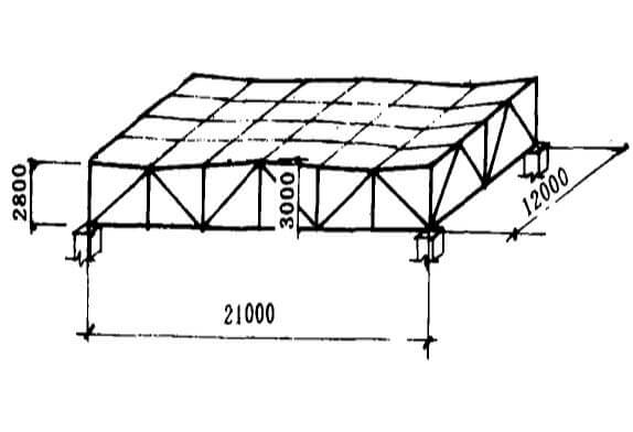
FIG. 3 Space frame scheme 2
Scheme 2 simultaneously raises the top chord at the top of the column and the top chord at the mid-span, which not only meets the drainage requirements but also makes the members more reasonable in stress. In the force analysis, it can be seen from Figure 1 that the space frame rod forms an arch formed by a thick black line and the tension cable is shown by the dotted line, and the horizontal tension of the arch is borne by the lower chord. The arch line under compression and the cable line under tension is basically close to the main compression line and the main tension line when the beam is bent; obviously, the stress is reasonable.
Table 1 Comparison of indexes in 21.0×12.0m column network
|
Pipe quantity |
Pipe quantity |
Nodes quantity |
Max size of ventilating ducts that can pass through the space frame |
|
|
Scheme I |
168 |
585.3 |
48 |
1.2m*1.2m |
|
Scheme II |
120 |
406.5 |
36 |
1.5m*1.5m |
|
Comparison of quantity between two schemes
|
1:0.71 |
406.5 |
1:0.75 |
1:1.56(area ratio)
|
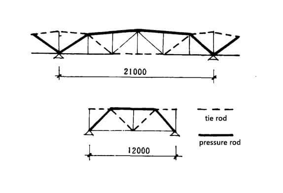
FIG. 4 Internal force analysis diagram
Combined with the characteristics of this project, the maximum pressure of the web rod at the bearing is 900kN, and the length is 4.36m. Obviously, steel pipe is more suitable than angle steel. For the joint form, construction units tend to use welded balls. In addition, since the angle between the bearing web and the lower chord is only 36°36′, if a bolt ball is used, the diameter of the ball will be too large. Finally, it is decided to use steel pipe welded hollow ball joint space frame.
1. Data related to spaceframe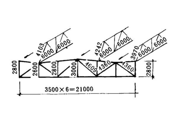 Figure 5. Diagram of space frame size
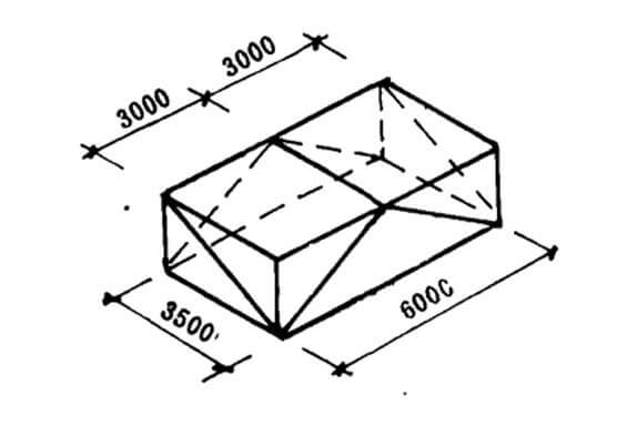 FIG. 6 Schematic diagram of space frame size
The size of the mesh in the 21.0m direction is shown in Figure 5, and the center distance between the upper and lower nodes of the straight web rod is 2.6m, 2.8m, and 3.0m. The 12.0m-direction mesh is formed into two herringbone shapes, and the upper and lower chord nodes at both ends are respectively connected to the corresponding nodes of the 21.0m-span mesh. Since the spacing between the 21.0m cross-mesh pieces is 6.0m, and the 12.0m long mesh piece spacing is 3.5m, this constitutes a basic mesh with a lower chord space frame size of 3.5mX6.0m and an upper chord space frame size of 3.5mX3.0m ( Image 6). The entire factory building space frame is composed of 3780 such basic space frames.
Table 2 Component quantity sheet
|
Pipe quantity |
Nodes quantity |
Total weight of pipes |
||
|
Supporting nodes |
Other nodes |
Total |
1900t |
||
| 315 |
40400 |
528 |
11990 |
12518 |
|
The pipes used for the space frame are: ∅70X4, ∅76X4, ∅89X4,∅102X3, ∅114X4.5, φ140X6, ∅159X8, ∅180X9 and ∅180X14, bolt ball specifications are: 2510, ∅3514, ∅3516 and∅4014, pipes smaller than ∅70 are not selected because the suspension load of the space frame is large and the rods are long to ensure the stability of the rods. If the diameter of the ball is selected according to the specification, and the rod is left with a distance of about 2cm on the spherical surface, a large number of balls with a diameter of 52cm will be used, which will greatly increase the amount of steel used. In the design, the method of adding a splint at the junction between the rods is adopted to reduce the diameter of the ball.
2.The installation of the space frame
The space frame of this project adopts a unique method, which avoids the construction method full of scaffolding and adopts three methods to install the space frame. Scheme 1 is shown in Figure 7. First, assemble the 21.0mX6.0m space frame unit on the ground, and then hoist the adjacent two 21.0mX6.0m space frame units in place. In the air, the 6.0m long upper and lower chords will be installed. The mesh composed of two web rods is welded with the 21.0m span mesh nodes on the two sides, and the installation of the entire mesh frame is gradually completed. The second plan is to assemble the 84.0mX84.0m and 84.0mX105.0m space frames on the ground, and then hoist them into place with 12 and 16 pick rods respectively. The third plan is to build a small platform, assemble the 21.0mX12.0m space frame in the air, and then drag the platform on the track to the next station to continue assembling.
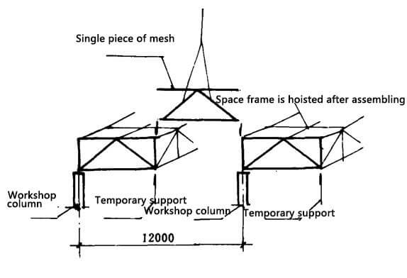
FIG. 7 Hoisting method
Copyright © Xuzhou LF Engineering & Construction Co., Ltd. All Rights Reserved.

 +86-17751936871
 +86-516-8595-0258


