

+86 177 5198 6706
222, Block B, Diamond International, Guozhuang Road, Xuzhou, Jiangsu, China
1、Project Overview
(Indonesia) Poya 2×660 MW Pithead Power Station supporting coal storage yard dry coal shed space frame project (Fig. 1) Located in the south of MuaraEnim County, South Sumatra, Indonesia, about 3.5 km southeast of Darmo Town . The longitudinal length of the space frameproject is 220 m, the lateral width is 128.24 m, and the unfolded area is about 38,000 m2. The space frame form is a positive quadrangular pyramid, and the support form is a bottom chord support. The space frame of the dry coal shed is a cylindrical reticulated shell structure, the bolt ball joints are of the positive quadrangular cone type, the span directions are the A and B axes, the span is 120.8 m, the longitudinal axis is 1 to 54 axes, and the total length is 220 m. The distance between axes 18 to 19 and axes 36 to 37 is 8 m, the rest of the axes are 4 m apart, the top elevation of the reticulated shell is +41.950 m, and the top elevation of the skylight is +44.928 m. The space frame members of this project are made of high-frequency welded pipes and seamless steel pipes, and the material is Q345B. High-strength bolts with diameters of M20 to M36 are grade 10.9, and those with diameters larger than M36 are grade 9.8. The bolt balls are made of 45-gauge steel, and the sealing plate cone head is made of Q235B or Q345B steel. The net frame above the support is a cylindrical shell structure, the width at the support of the net frame is 120.8 m, the space frame sag height is 34 m, and the distance between the upper and lower chords is 3.8 m.

Figure 1 Project site
2、The space frame installation technology
2.1 Beginning of space frame installation
Starting from axes 26 to 28, after the completion of the starting span, the construction will be divided into two groups on both sides of the starting span to the direction of axis 01 and axis 54 respectively. On the ground, install the three space frame of 26, 27, 28 from the lower string ball at the B-axis support to the A-axis, and use a 50 t crane to hoist the space frame at one end of the A-axis on the ground and put it in place. . The support body and the support ball at the B axis are not welded, and the φ14 steel bar is used as the ball hoop, and the ball can rotate in the support. A 50 t crane is used to lift the front end of the space frame, and a 25 t crane is used to assemble the small unit triangular cone space frame. While adjusting the lifting point, assemble it on the ground in the direction of the B axis, as shown in Figure 2. There are a total of 15 bolt balls in the installation unit of the starting space frame, and the weight of 39 rods is about 5.8 t.
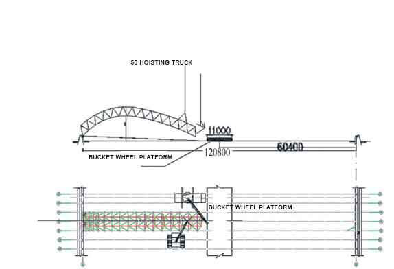
Figure 2 Design of crane selection scheme
2.2 Use 50 t crawler crane and 25 t truck crane to cooperate with the space frame to continue to extend across the bucket turbine. The lifting point of the 50 t crane is between the 15th and 16th bolt balls from the B axis to the A axis direction. At this time, the lifting point The force is 18.6 tons, the hoisting radius of the 50-ton crane is 7.0 meters, and the hoisting weight is 21.4 tons, which is greater than 18.6 tons, which meets the requirements. The space frame is spliced here, the net frame is placed on the ground, and the net frame is lifted by a 260 t crawler crane (the lifting point is between the 15th and 16th ball nodes of the A-axis starting and winding chord, and the reaction force of the lifting point is 185.6 kN, continue to start Assemble the space frame, as shown in Figure 3. Analysis of hoisting conditions: the parking position of the 260 t crane is on the west side of the bucket turbine and the south side of the space frame, close to the 26th axis, and the hoisting radius is not more than 14 m at this time, as shown in Figure 4 The maximum reaction force received by the crane hook is 185.6 kN. At this time, the hoisting capacity is 53.6 t, which is greater than 185.6 kN, and the crane meets the requirements.
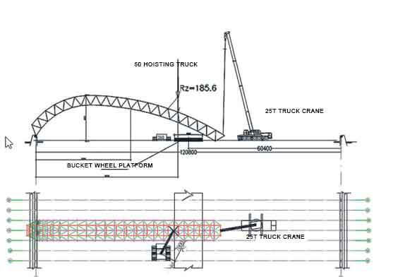
Figure 3 Two belt trucks cooperate across the bucket wheel platform
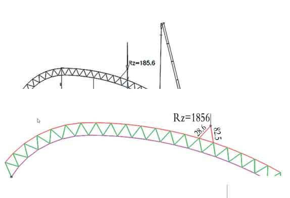
Figure 4 Using a crane (260 t) lifting point and wire rope force analysis
2.3 The 260 t crane and 180 t crane are used for hoisting to complete the ground assembly of the starting space frame with a projected length of 114 m. The hoisting conditions are shown in Figure 5 and Figure 6.
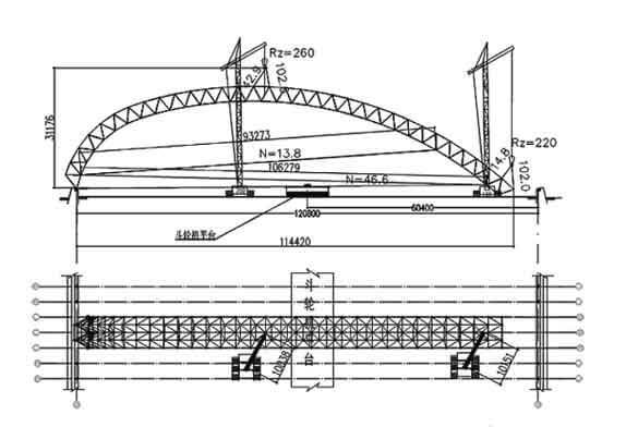
Figure 5 Adjust the lifting point and continue the installation
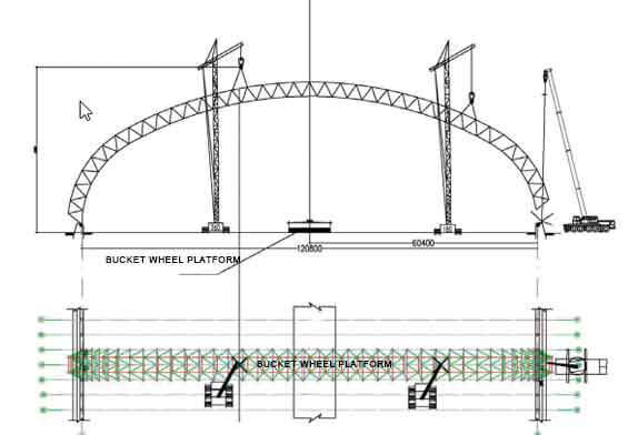
Figure 6 The working conditions before the completion of the starting space frame
2.4 After the above-mentioned hoisting and assembly are completed, the three cranes will simultaneously carry out the work of placing the support of the space frame. When the starting space frame is close to the support position, align the center line of the support for fine adjustment. After the support is in place, temporarily fix the base plate of the support and the embedded parts with limit steel plates in advance, or temporarily weld the transition plate and the embedded parts, as shown in Figure 7. At the same time, it is about 20 m in the middle and on both sides of the space frame. Three ropes of φ16 steel wire ropes (6 ropes in total) shall be installed on each side of the place as cable wind ropes to avoid the deformation and overturning of the space frame. After the three rope wind ropes are arranged, the crane can be evacuated. The pre-buried anchor bolts on the foundation of the bucket turbine are used as cable wind rope ground anchors, as shown in Figure 8.
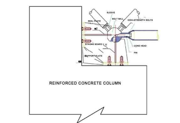
Figure 7 Space frame support diagram
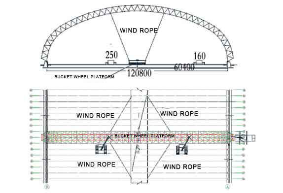
Figure 8 Layout of the cable wind rope
2.5 Support position After the expansion installation of the space frame is completed, the crane is not completely unloaded, and it is still in working condition. Mounted along the length of the frame up to axes 25 and 29 (installation width at the support up to 16 m). Install another span to both sides at the support positions at both ends of the starting space frame. After installing 6 to 8 space frame in the span direction, the crane can be evacuated. The cable wind ropes on both sides are still retained, and the installation of the starting space frame is completed.
2.6 Subsequent space frame installation
The space frame is longitudinally installed by the small vertebral body high-altitude bulk method, and the cable wind rope can be released after the installation of the 2-span space frame is completed. Then install subsequent space frame until the overall installation is complete.
3 Calculation of lifting wire rope
Wire rope length check: The length of each wire rope is 12 m, and the calculation adopts model space lofting to provide a force diagram according to the design. The maximum force of a single wire rope is 140.7 kN. The allowable tensile force of the wire rope is calculated according to the following formula: [Fg]=αFg / K ≥ F (1) In the formula: [Fg] refers to the allowable tensile force of the wire rope; Fg refers to the sum of the breaking tensile force of the wire rope; α refers to the load non-uniformity coefficient between the wire ropes, Take 0.85, 0.82 and 0.8 for the wire ropes of 6×19, 6×37 and 6×61 respectively; K refers to the safety factor of the wire rope. The steel wire rope with the ultimate strength of 2000 N/mm2 is selected for the hoisting wire rope of the space frame, α is taken as 0.82, and the safety factor is taken as 8. Choose a wire rope with a diameter of not less than φ43. [Fg]=αFg /K=0.82×1390/8=142.5 kN Since 142.5 kN > 140.7 kN, the requirement is satisfied.
4. Conclusion This paper takes the installation of the dry coal shed space frame project in the coal storage yard supporting the Poya 2×660 MW pithead power station as an example, and focuses on introducing new technologies and new methods for the hoisting of the space frame project with high risk, and aims at it. Effective analysis and verification of structural hoisting under different working conditions at each stage,
Copyright © Xuzhou LF Engineering & Construction Co., Ltd. All Rights Reserved.

 +86-17751936871
 +86-516-8595-0258


