

+86 177 5193 6871
222, Block B, Diamond International, Guozhuang Road, Xuzhou, Jiangsu, China
Yiyang Stadium is a medium-sized stadium with 20,000 people. The outline of the stadium is an ellipse with a short axis of 180m and a long axis of 200m((see Figure 1). The roof of the east and west stands is a steel-cable-membrane structure. The space curved structure is mainly composed of rectangular lattice steel columns with variable sections, monolithic truss steel columns, inner ring beam (triangular lattice), central beam (triangular lattice), outer ring beam of steel pipe, suspended steel truss, radial steel truss, pull rod, strut rod, pull film rod, cable film, etc. All members are welded by seamless steel pipe. The structural form is that triangular cantilevered steel trusses radiate from each rectangular steel lattice steel column with variable sections at different angles. The tip and tail of the trusses are connected to the top of the steel column with steel cables, thus forming a load-bearing support structure similar to the form of a tower crane, and then connected to other components (inner and outer ring beams, etc.) to form a spatially stable structure (see Figure 2). The total amount of steel used in the project is about 600t, the maximum installation height is about 50m, and the installation weight of a single piece is about 20t, of which the cantilevered steel truss weighs about 6t, the maximum cantilever span is 27m, and the tip cantilever elevation is +34.400m.
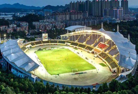
Figure.1 stadium membrane roofs
1.1 The structural system is complex and the membrane roof structure is an interactive space structure system composed of radial cantilever steel trusses, columns, ring beams, rods, struts, and cable membranes (see Figure 1). Before and after the installation of the structure, the stress conditions of each part of the whole system are different. In order to make the stress of the structural system consistent with the design parameters, simulation calculations should be carried out for each working condition of the structure.

Figure.2 a(Schematic cross-section of steel truss) and b(Schematic cross-section of steel truss)
1.2 The structure is difficult to hoist
The cantilevered steel truss has a large span, low stiffness, high installation height, and a small inclination angle. There is no lateral constraint during the hoisting process, and the spatial stability is poor. Therefore, in the hoisting stage, it is necessary to carry out construction checks on the reaction force, deflection, internal force of the rod, and the stability of the temporary position, etc., and the hoisting command and operation are difficult.
1.3 The welding quality requirement is high. The butt weld of the steel truss is a full penetration weld, and the quality grade is first class. The welding of the intersecting line between the main pipe and the belly bar joint on-site is complicated (see Figure 2). The number of thick steel plate welding is large, and 40% of the welds are of small Angle (< 30°) weld, high welding quantity. A reasonable welding process must be selected to reduce welding stress and deformation.
1.4 Positioning and measurement accuracy requirements are high
The hoisting positioning and measurement accuracy of the entire structure is mainly reflected in the temporary stability and measurement positioning of the cantilevered steel truss. The cantilevered steel truss has a large span, long and slender dimensions, uncertain factors such as rod deformation, and is welded at the root, and the stay cable above the suspended end is tied to the top of the column. The factors involved in the production length control and the reserved height control of the tip of the brace are complicated, and the installation accuracy of each unit affects each other. The entire venue plane is composed of several circular arcs with different diameters, which are approximately elliptical. The center of the structural steel column is positioned as three-dimensional data. The size of the positioning error is crucial to the positioning of the cantilevered steel truss structure system and the installation of the inner ring beam.
1.5High requirements for installation coordination
The entire structural system is basically symmetrical, and each basic unit is similar. But the length of each unit is different, the elevation is different, the model of the sub-bar is different, and the cross-sectional size and length are different. At the same time, the truss and the lattice steel column are rigidly connected, combined with the flexible connection of the upper and lower cables, which is different from the conventional steel structure installation in many aspects such as installation concept, installation method, control measures, and coordination.
According to the structural design characteristics and the construction conditions that the crane cannot enter the stadium, 150t crawler crane is selected as the main crane equipment to lift the steel column, longitudinal suspension steel truss, central beam, radial steel truss, inner ring beam and other long, heavy and distant components outside the stadium. The rest of the light components are installed with winches and inverted chains.The hoisting sequence of each unit is as follows: steel column hoisting → central beam hoisting → suspended steel truss hoisting → steel cable installation on suspended steel truss → radial steel truss hoisting → inner ring beam hoisting → light rod installation such as tie rod, strut rod and outer ring beam installation → cable film installation.
2.1 Steel column hoisting
The steel column adopts one-point binding and sliding rotating lifting. To avoid the deformation of steel column feet during lifting, the column feet need to be strengthened. The sling is bound at 2/3 of the column body away from the column feet (that is, at the connecting node of the tie rod at the root of the suspension truss), and an auxiliary iron pole is set at the hook of the sling to ensure that the column can be lifted smoothly into the vertical state. When the column is in position, align the center line marked in advance on the foot of the steel pipe column with the center line of the base cross positioning using a ruler. The hook is slowly lowered into place, and at the same time, four wind ropes are pulled from the top of the column to the ground for temporary fixing and correction (see Figure 3(a)). After the perpendicality of the column and the position of the plane axis is corrected, the four steel pipe column feet should be welded symmetrically at the same time, and the hook can be loosened after 1 pass of welding. After the hook is loosened, the perpendicality of the column should be reviewed for timely correction.

Figure.3 a(Steel frame column crane) and b(Steel truss hanging)
2.2 For the hoisting of the central beam, cantilevered steel truss, radial steel truss, and other components, a 150t track crane is used for two-point binding and hoisting with one through cable, as shown in Figure 3(b), and a pair of 2t inverted chain is attached for Angle adjustment to ensure accurate emplacement. After emplacement, wind rope is used for temporary stabilization and proofreading on both sides of the end of the component.
(1) The male fixation point of the cable wind rope used for measurement and correction of all large components is the M20 expansion bolt plate on the concrete slab of the grandstand.
(2) To enhance the stability of the suspension steel truss, cable installation must be carried out at the same time as hoisting. If the cable installation cannot keep up, 432 round steel (No. 45 steel) tie rods should be used to connect the two lower strings of the truss to the steel column and the concrete column of the grandstand for temporary fixing.
(3) To facilitate the correction of the cantilever steel truss and the overall lifting of the inner ring beam element, a medium 377mmx6mm steel pipe support should be set up from the ground at the forearm of the cantilever truss. At the same time, an operating platform and a lifting adjusting bull leg should be set up at the top of the steel pipe support . The bottom of the support is fixed with the M20 expansion bolt plate and is stabilized with four No. 8 channel steel diagonal braces. At the position 3.0m away from the top of the steel pipe support, four wind ropes are pulled to the ground for stabilization.
4) In order to ensure convenient operation, ladders and springboards shall be hung on each column body and on the lower chord surface of the cantilever steel truss.
Through safe and secure installation technology, the membrane top steel structure with complex space and poor stability is successfully installed by conventional mechanical lifting equipment in a relatively short time. Through the use of special technical measures, save a lot of project costs, shorten the construction period. Process flow and hydropower installation and other subsequent projects form flow operation, reasonable construction layout and cycle arrangement.
Copyright © Xuzhou LF Engineering & Construction Co., Ltd. All Rights Reserved.

 +86-17751936871
 +86-516-8595-0258


