

+86 177 5193 6871
222, Block B, Diamond International, Guozhuang Road, Xuzhou, Jiangsu, China
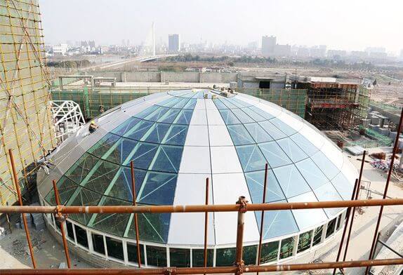
1. Glass Dome Roof Project Overview
The total construction area of a glass dome roof project is about 20 000 m², the roof adopts a cable rod pre-stressed dome structure system, the dome radius is 29.5m, and the dome top elevation is 17.5m. Curtain wall dome project volume is about 3 300 m2, the glass is 8+2.28PVB+8+12A+10 double tempered laminated hollow low-E glass. The project volume of the facade curtain wall is about 620m2, and the glass is 12+12A+12 double tempered hollow low-E glass.
2. Scheme Selection
The components are cut and fabricated in the factory by computer-aided control and transported to the site for welding into a steel tube truss. Load according to the structure and the construction load tooling design support base and tooling support, will be the center of the dome at the top of the circular truss erection on tooling bracket, requirements, and meet the design elevation and the axis symmetry again will each stick main truss hoisting welding in order to support and circular truss construction process for each stick on the main truss pre-stressed cable plus partial stress, reduce the load tooling support and the main girder After the completion of the truss, the secondary truss is installed, and the remaining stress is applied to the pre-stressed cable, and the adjustment is repeated to meet the requirements of stress and deformation coordination, and the fixture support is removed.
3. Glass Dome Roof Construction process and operation points
3.1 Construction process
Production of dome components in the factory → bearing installation and construction → welding of on-site components → installation of central support frame → installation of central ring truss → installation of the main truss → installation of pre-stress cable and initial tension → installation of secondary truss (support) → final tension of pre-stressed cable → anti-corrosion paint painting → removal of the support frame.
3.2 Glass Dome Roof Steel Structure Installation and construction of support
After confirming the accuracy of control coordinate points and elevation points, the total station is used to locate the concrete column supporting 16 trusses of the main truss, measure its axis, control line, and elevation, and arrange special personnel to calibrate it to ensure measurement accuracy. Concrete pouring to the elevation of the bearing should be a timely arrangement of embedded bearing parts, with the total station instrument every 0.5 h to check the control line and elevation of embedded parts, until the concrete final setting, to ensure the installation accuracy of the bearing.
3.3 Site component welding
1)When welding components, weld the main truss first and then the secondary truss. Considering the small problems in the construction site, the main truss welding is divided into three times. First, part of the main truss is welded, and the main truss is installed immediately after acceptance. The truss steel pipes are welded on special birth-ware, which uses section steel above no.20 channel steel as columns and beams. The birth were is fixed by spot welding according to the actual distance between steel pipes, and the column Angle is fully welded. Use a hand hoist to set up the steel tube truss to the brackets, each main truss is set up 6 brackets, the secondary truss is set up with 3 brackets and evenly arranged.
2) according to the characteristics and design requirements of the project prepare a detailed welding special construction plan, and strictly according to the construction plan.
3.4 Erection of central support frame
3.4.1 The data for the dome’s central support structure were calculated in detail and combined with the comments of the panel. The fixture bracket is supported by a steel pipe fastener type scaffold system of φ48mm×3.6mm, the plane size is 9000mm×9000mm, the vertical distance and transverse distance of the pole are 500mm, and the step distance is 1200mm. The top of the pole (the bottom of the ring truss) is a one-way length set [10 steel as the bearing surface of the circular truss, the spacing is 500mm, and is fixed on the top of the pole in reverse.
The ground shall be back-filled with brick and slag with a thickness of 200mm each time, and compacted layer by layer with a road roller. The back-filled depth at the center where scaffolding is installed shall be 1000mm.
3.4.2 The distance between vertical rods shall be set strictly in accordance with the technical parameters in the scheme and the relevant provisions of the vertical rod joints in the specifications. The joints are staggered, and the distance between the center of each joint and the main node is no more than 400mm.
3.4.3 The crossbar must be set continuously in both vertical and horizontal directions. The crossbar in the same step is surrounded by intersecting rings, and the joints are staggered. The horizontal distance between adjacent joints is no less than 500mm, the distance between the joints in this project and the column is no more than 150mm, and the horizontal height difference between the crossbar and the column is no more than 30mm. The sweeping rod shall be set according to the specification.
3.4.4 Starting from the sweeping rod, there is 1 line for every 6 steps. The tooling support is provided with 3 lines of horizontal scissors support. The vertical scissors support is arranged continuously on all four sides of the tooling support, and one line is arranged every six rows in the vertical and horizontal direction of the support. Scissor support and vertical rod or bar fixed, the fixed point from the main node distance is not more than 150mm, the bottom end of the diagonal rod and the backing plate tight.
3.4.5 Protective facilities
The outer side of the whole tooling support is hung with a dense mesh safety net; The top of the tooling support, not only supports the dome annular pipe truss, but also the roof assembly platform, so a temporary staircase to reach the top of the tooling support, a 1000mm high guardrail around the top, and covered with foot plates.
3.5 Installation of center ring truss
The two ring trusses in the center of the dome were lifted to the fixture support by a 30T crane, the central ring truss was positioned with total station instrument, and the horizontal flatness and verticality of the top [10 steel platform] of the fixture support were checked to ensure that the space of the central ring truss was placed accurately.
3.6 Installation of the main truss
The main truss is installed using the comprehensive internode method, that is, the main truss is installed symmetrically and the prestressed cables under the main truss are installed in place and the initial tension is completed. When the main truss is installed in pairs, double cranes (2 sets of 130T) are used to lift 1 bar of the main truss at the same time, slowly lift to the ring truss position, and connect and weld with the top ring truss. At the same time, the other end of the column support is in place, install and tighten high-strength bolts. During this period, the crane has been in the lifting state until the high-strength bolts are fastened and the welding is finished, and the crane can release the hook. And so on, piece by piece, until all the main trusses have been installed.
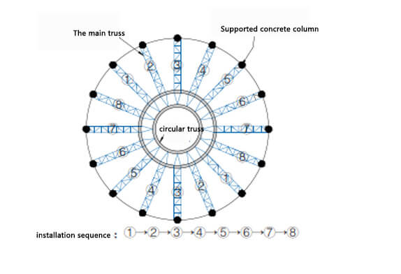
FIG.1 dome roof Installation sequence

FIG. 2 Elevation diagram of the connection between ring truss and main truss(a) and Plane diagram of the connection between ring truss and main truss(b)
3.7 Installation and initial tension of a pre-stressed cable
Before the truss is installed, the pre-stressed cable nodes on the truss (including the main truss and the bottom ring truss) are numbered, the pre-stressed cable nodes are opened in advance on the ground, and the pre-stressed cable is installed to the pre-stressed cable nodes according to the number by the crane, and the pre-stressed cable is tightened with the hand pulling hoist. Only one end of the pre-stressed cable of the bottom ring truss is installed on the node, while both ends of the pre-stressed cable of the main truss are installed on the node.
After the installation of the main truss, the pre-stressed cable is preliminary tension. The pre-stressed cable is divided into preliminary tension and final tension, and the pre-stress value is 70% and 100% of the design value respectively. The other end of the balanced pre-stressed cable of the bottom ring truss is symmetrically suspended to the cable node by a crane. The prestressed cable is tensioned with a hand hoist, and the steel pin is inserted for initial tensioning. The initial tension stress is 70% of the design value, and the initial tension is symmetric. 3.8 Installation of secondary trusses (supports) The integrated internode method was also used for the installation of secondary trusses. Double cranes (2 sets of 130T) were used to symmetrically lift a span sub-truss at the same time, slowly lift it to between the two main trusses, and connect it with the main truss for welding. After the symmetrical two-span truss is welded, the crane can release the hook. In this way, the secondary truss is symmetrically welded step by step.
Copyright © Xuzhou LF Engineering & Construction Co., Ltd. All Rights Reserved.

 +86-17751936871
 +86-516-8595-0258


