

+86 177 5193 6871
222, Block B, Diamond International, Guozhuang Road, Xuzhou, Jiangsu, China
In the construction of many long-span projects, the space frame structure will be considered, and it is more and more widely used. At the same time, with the continuous improvement of our country’s social development level and the gradual strengthening of the economy, there are more and more applications of large-span steel structure space frames, and related technologies are also being continuously improved. In urban construction, the construction of many factories and infrastructure requires the construction and application of a large number of space frame projects. Therefore, the requirements for the construction technology of space frames in our country are getting higher and higher.
This project is a construction project of production houses and supporting facilities, among which the supporting facilities focus on the bulk stock yard shed space frame. The space frame project is a screwball welded ball structure. The specific structure is an orthogonal and orthogonal square pyramid welded ball joint. The main structure is a three-layer space frame structure with a horizontal lower chord and a flat double slope on the upper chord. The arrow heights of the space frame are 4m and 2.2m respectively. , the joints are connected by bolt ball + welded ball joints and are supported at the lower chord point. The steel material used in this project has strong tensile strength and elongation, and the sulfur and phosphorus content can also be guaranteed qualified, through the carbon content and cold bending test.
The installation height of the space frame structure (as shown in Figure 1) is 28m, and the projected area of a single area reaches 10,000 square meters, which is divided into two areas. The project has the characteristics of heavy rods and a large number of rods. If conventional high-altitude bulk work is used, a large number of scaffolds will be used, which not only involves a lot of high-altitude operations but also adds great difficulty to the construction.
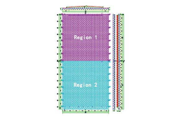
Figure 1 Schematic diagram of space frame
This project belongs to the type of flat space frame, but its own span is large, at the same time the main body is composed of three layers of the space frame, coupled with the joint welding method for bolt ball and welding ball mixed, so the overall structure is complex and the construction is difficult. Technical and managerial responses need to be refined in many ways.As a multi-project cross operation, the project has the characteristics of large quantities of work, coupled with a tight schedule, so the construction difficulty is high, need to combine the existing construction technology and measures to do a good job in construction management, integration of construction plans to further optimize, improve the technical level of the construction team, pay attention to the coordination between different projects, Implement various safeguard measures in logistics such as material supply. The support divides the entire network frame into two parts. Due to the heavy weight of each space frame and the high height of the column structure, it is difficult to assemble and lift the space frame. Compared with conventional construction, it needs to use a lot of manpower and material resources. Therefore, based on these difficulties in construction, it is necessary to put forward some targeted technical points and measures. The applied construction technology needs to be advanced, rational, and safe; steel as the main construction material needs to be provided by large-scale domestic steel production enterprises, and necessary rust removal treatment is required after the components are manufactured. The painting should be completed within 6 hours after the rust removal treatment, and the overall quality of the steel structure components must comply with the steel structure engineering construction quality acceptance specification. All steel materials and connecting materials used in the construction of the project need to issue quality certificates, which meet the current national standards. Generally speaking, how to follow the relevant standards and technical requirements to carry out project construction and ensure construction safety is a major difficulty in this project.
In view of the difficulty in installation and construction of this project and the high safety risks, the final study decided to use the hydraulic synchronous lifting technology for super-large components to lift the components in place, and then install the support and rod parts. This construction method has to help improve construction efficiency and reduce construction difficulty, the project will also be divided into two areas for upgrading construction.
To use hydraulic synchronous lifting means to complete the hoisting of the space frame, it is first necessary to set up the lifting platform on the support system, and then configure the hydraulic lifting equipment on the lifting platform, and the whole space frame needs to be assembled on the ground, that is, the whole Lift the space frame structure and lift it to the predetermined height at one time, and it can be completed. Combined with the site conditions of this project, it is necessary to avoid collisions between the space frame and the concrete structural columns during the lifting process. Therefore, during the space frame assembly process, the support connecting rods on the columns are not installed.Install it after lifting it to a predetermined height. During the construction, the special steel strands are directly connected to the lifting points under the hoisting space frame structure, and then the telescopic cylinder process of the hydraulic lifter equipment is used to lift the steel structure to the design position. After reaching the predetermined height, the butt joint welding and installation of supplementary rods can be realized.
First of all, in order to ensure that the lifting of the space frame structure remains stable and has enough lifting force, the total weight of the space frame structure of the stockpiling greenhouses in each area must be defined first, and the specific position of the lifting point must be determined. The limit value of the hydraulic hoist at each lifting point must be higher than the calculation upper limit of the average lifting point, and the hoist specifications are the same. Only in this way can it be applied to the space frame construction of the stockpiling greenhouses. Secondly, during the configuration of the hydraulic pump source system, managers need to judge the reaction force value according to the number and layout of the lifters, so that the hydraulic pump source system can continue to be in a stable operating state. During the period, according to the actual situation of the project, the pump source was selected as the TJV-60 model, and each pump source equipment controlled up to 4 hydraulic lifters; again, in order to ensure that the pump source system and the hoist could be controlled, the project also needed to provide computer equipment and transmission. Finally, in the process of selecting load-bearing steel strands, it should be determined that the load-bearing limit of the steel strands is higher than the gravity of the lifting point, and the steel strands have no obvious signs of damage, so as to avoid damage to the hydraulic lifting system.
In order to ensure the stable upgrading of the space frame structure and meet the requirements of construction safety, the engineering management personnel should review the quality of the synchronous control system based on the location of the space frame lifting points, and check whether the oil pressure balance at the lifting points, the stability of the structure, the effect of synchronous displacement control, and the installation of the hierarchical unloading system. During this period, the synchronous control system must determine the potential risk factors based on the project site environment, and try to avoid damage to the life and property safety of the construction site personnel, so as to ensure the quality of the stacking greenhouse space frame construction and to provide a more comprehensive guarantee for the use of the subsequent engineering system. During this period, the management personnel must ensure that the lifting points of the same motor in the pump station bear the uniform load, and ensure that the length and operation of the steel strands meet the stability requirements so that the moving speed of all lifting points is consistent and the space frame lifting process can continue.
How to use the super-large component hydraulic synchronous lifting construction technology in this project is extremely important, which is related to the final construction effect of the greenhouse space frame. Therefore, it is necessary to conduct an in-depth exploration, and conduct the following analysis on the key points, mainly including the following points:
During the lifting point setting, the project management personnel must determine the appropriate lifting point position according to the steel distribution of the greenhouse space frame, ensure that the connection stiffness of the lifting parts is enough to bear the shared weight, and the lifting point distribution is uniform without obvious load inclination so that the transportation of the space frame can be kept in a stable state. In addition, during the selection of lifting points, it is necessary to ensure that the basic structure of the lifter equipment meets the requirements of the stability of the bearing capacity, and the steel beam at the lifting point must be the main beam of the space frame, which can bear the overall quality of the steel space frame. Avoid situations such as lifting and instability of the steel space frame, so as to provide a more comprehensive guarantee for the safety of the life and property of construction personnel. According to the engineering data, 16 lifting points are set on both sides of the steel space frame in this project, and the corresponding positions of each lifting point are consistent with the bearing surface position of the concrete column on the site so that the overall structure of the space frame can be stable when it falls on the concrete column. See Figure 2 for the specific lifting point Settings.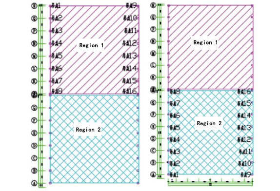
Figure 2 Plane layout of hoisting points
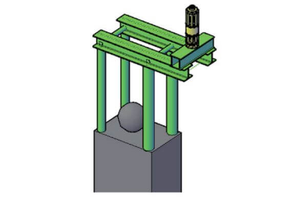
Figure 3 Three-dimensional schematic diagram of lifting bracket
Combined with Figure 3, it can be seen that the location of the lifting point needs to be clarified. According to the basic characteristics of the space frame structure system, the value of the lifting reaction force is determined, a flexible lifting support system is added to the column member, and the weld components at the top of the column and the column foot are carried out. Effective welding and reasonable control of the bracket system. In the first stage, the position of the lifting point should be determined. After the position is lifted, the sequence of rod repairs should be determined to avoid affecting the lever system of other parts. In the second stage, the lifting bracket is removed, and other rods are supplemented. After the construction task of the previous link is completed, the bracket cannot be removed directly, the steel strand is tightened, and a certain force is applied. In this case, The bracket still plays a supporting role. After the installation of the workpiece that has nothing to do with the position bar is completed, the corresponding disassembly work can be carried out. According to the correct disassembly sequence, the support bracket is gradually decomposed to make the steel strands lose. After the design conditions are met, the disassembly can be checked.After the disassembly is completed, recover the bracket components, set up suitable lifting points, and set up and implement the disassembly work in accordance with the standard sequence. Fillet welds can be used for stiffened rib plate members, and the chamfer and openings of the members should be ground flat to prevent excessive stress concentration and always maintain the stability of the space frame structure. The actual construction process also needs to be based on the corresponding schematic diagram, then set up the bracket, determine the appropriate location of the lifting point.
According to the diagram of the reinforcing rod at the support of the original structure (FIG. 4), it can be seen that reasonable reinforcing rod operation should be carried out after the space frame is raised to the designated position. In the process of reinforcing the rod, the accurate position of the reinforcing rod should be ensured to ensure the rationalization of reinforcing rod work. Make up the rods at the non-interference position first, then remove the lifting bracket to provide a place for the later repair rods, and finally install other rods that need to be supplemented reasonably. During the entire rod repairing operation, there are several points for attention: first, after the rod repairing operation is performed on the non-interference position, the removal work cannot be carried out immediately, because the lifting bracket is used as a support result, once the supporting structure is removed in advance, it will affect the stability of the entire lifting and hoisting device, and uncontrollable consequences will occur. For this reason, it is necessary to control the removal time. Install the non-interfering patch bars one by one to ensure that after all the patch bars are installed, the lifting bracket can be removed. During the dismantling process, the steel strands need to be loosened according to certain rules. Generally, we follow the rules of 20%, 40%, 60%, and 80% to 100% to relax the steel strands. The yellow bracket in the picture is the non-interference repair rod, the pink part is the post-repair rod, and the green part is the lifting bracket, you can clearly see the effect picture after the rod repair.
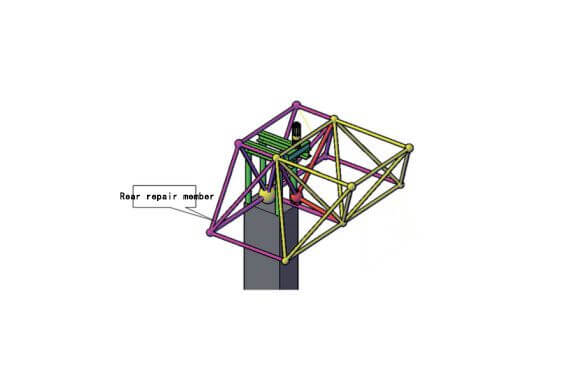
Figure 4 Schematic diagram of the supplementary rod at the support of the original structure
All in all, the development trend of steel structure engineering is that the structure is becoming more and more complex, and the scale of the project is also expanding. If the simple installation method and installation technology are still used, it will not be able to meet the actual needs of the project. The construction of steel structure engineering needs to use a series of complex technical systems, and it is necessary to combine and apply a variety of construction technologies and construction methods, so as to ensure the overall quality of the project.
Copyright © Xuzhou LF Engineering & Construction Co., Ltd. All Rights Reserved.

 +86-17751936871
 +86-516-8595-0258


