

+86 177 5193 6871
222, Block B, Diamond International, Guozhuang Road, Xuzhou, Jiangsu, China
The space frame structure canopy is connected by steel rods through nodes, forming a construction mode with high spatial rigidity, good integrity and simple assembly. The layout of the steel space frame structure is flexible, and can adapt to buildings with different spans, different plane shapes, and different functional requirements. The welding process and installation quality are controllable, which meets the objective requirements of building industrialization. Taking the construction of a space frame structure canopy at a toll station in Shenzhen as the background, the feasibility of the overall hoisting is verified by calculation through the process improvement of the space frame structure assembly and block-by-block overall hoisting.
1 、Project overview
A toll station in Shenzhen is designed as a main line toll station, with 7 entrances and 7 exits, a total of 14 lanes. The toll booth is a steel space frame structure, and the exterior decoration adopts glass curtain wall and aluminum veneer metal curtain wall. The plane size of the steel space frame is 74.2m×39.1m, the chord height is 6.46m, and the maximum single span is 16.5m. The space frame structure canopy is shown in Figure 1.
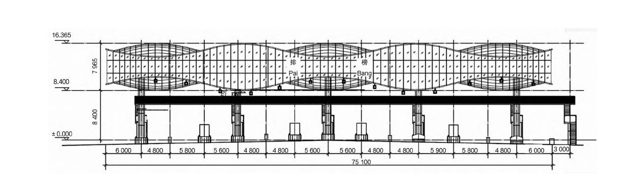
Figure 1 space frame structure canopy
The steel pipe is made of Q235B steel, the bolt ball is forged from No. 45 steel, the sleeve is made of Q235B steel, and the high-strength bolts are made of 10.9S strength grade; the steel keel is cold-formed by thin steel plate, and the material is Q235B; the roof and ceiling are sprayed with 3.0mm thick fluorocarbon Aluminum veneer; 70mm×50mm×4mm hot-dip galvanized steel pipe for main keel, 50mm×50mm×4mm hot-dip galvanized steel pipe for secondary keel; 6+1.14PVB+6 tempered laminated glass for facade glass curtain wall; 80mm for main keel ×60mm×5mm hot-dip galvanized steel pipe, 60mm×60mm×5mm hot-dip galvanized steel pipe for secondary keel.
2、 Overall hoisting analysis of blocks
2.1 space frame structure block
The space frame structure is assembled on the ground in the form of blocks, and the installation method is hoisted by a crane in blocks. The construction steps are: site and civil engineering handover → anchor bolt pre-embedding → steel column installation → steel column support installation → size review → erection of a simple assembly platform on the ground → space frame assembly → paint brushing → curtain wall skeleton production and installation → aluminum plate installation → Overall hoisting and splicing → Glass curtain wall installation → Horseway and stairway installation → Completion acceptance. The block diagram of the space frame structure canopy is shown in Figure 2.
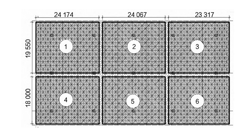
Figure 2 block diagram of space frame structure canopy
2.2 Block lifting analysis
Use the space steel structure software space frame to model, and analyze the stress of the space frame during hoisting. The model is shown in Figure 3.
Input the node load and surface load according to the code requirements, and then run the analysis. According to the calculation and analysis model inspection results, the structure can meet the calculation requirements of bearing capacity, and the maximum stress ratio is 0.68.
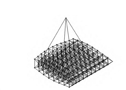
Figure 3 The force model of the space frame structure
3、 space frame structure canopy installation
3.1 Installation difficulties and solutions
Difficulties and solutions for the installation of space frame canopies are as follows.
(1) There are 15 steel frame support points in this space frame project. The precision of the embedded parts of the steel columns will directly affect the construction quality of the steel space frame, so the installation accuracy of the embedded bolts is very high. How to ensure the precise pre-embedding of the embedded bolts is one of the difficulties in this project. The solution is precise setting-out positioning, and the axis and elevation of the embedded parts are strictly controlled through the total station and the level.
(2) The area of the steel space frame of this project is relatively small, and the chord height is relatively high. Considering the actual situation that the installation height on site is not high, it will be installed by ground assembly, partial decoration and installation, and overall hoisting. How to ensure the precise positioning, installation quality and safe hoisting of the steel space frame is also the biggest difficulty of this project. The solution is to rationally arrange the construction sequence, increase the stability of the space frame, and reduce the installation of loose parts in the air. The use of a suitable type of crane is also the key to safe hoisting.
3.2 Installation steps
(1) Steel column installation. The shed of the toll station is composed of 15 circular pipe columns with a specification of φ630×14. The steel columns are fixed to the cap foundation through 12 sets of embedded bolts of M45×1570 specifications, and the steel columns are adjusted through the adjusting nuts at the bottom of the columns. After checking the verticality, perform secondary grouting at the bottom of the column to prepare for the installation of the upper space frame.
(2) The space frame structure is hoisted in blocks. The space frame of the ranking toll station is distributed according to the force of the column. Under the working condition that the checking calculation meets the hoisting requirements, a total of 6 lifting points are set according to the center point of the force to ensure that the force system of the original space frame does not change greatly. When using a bundled four-point hoisting, the installation steps are as follows.
Choose a good station for the crane on the left side, and install space frame ① in the second horizontal row. The area of the piece is 33×21=693m2, the weight of a single piece is about 51.22t, the lifting radius is 23.61m, and the installation radius is 20.22 m. The crane continues to install the end side ② space frame in the original position, the area of the piece is 20.59×21=432.39m2, the weight of a single piece is about 42t, the radius of the lifting operation is 19.83m, and the radius of the installation in place is 23.84m.
The crane is shifted to the right, and the station is selected to install the space frame No. ③ on the end side. The area of the piece is 20.59×21=432.39m2, the weight of a single piece is about 42t, the radius of lifting operation is 19.83m, and the radius of installation in place is 23.84m. Move the crane to the opposite position, and hoist according to the above steps in the order of ④, ⑤, and ⑥.
3.4 Installation Quality Assurance
The space frame of this project is arc-shaped, requiring high installation precision, and technical preparations must be made before construction, including technical training for steel space frame producers. During the construction, professional management personnel with high theoretical level and strong business quality are selected to organize the construction, and strictly implement the inspection procedures and strict management. The installation accuracy requirements of the space frame are as follows: the allowable deviation of the finished length of the steel pipe rod is ±1mm; the straightness of the axis of the rod is L/1000 and not greater than 5mm; the assembly and installation of the steel space frame meet the requirements of the specification.
Copyright © Xuzhou LF Engineering & Construction Co., Ltd. All Rights Reserved.

 +86-17751936871
 +86-516-8595-0258


