

+86 177 5193 6871
222, Block B, Diamond International, Guozhuang Road, Xuzhou, Jiangsu, China
The space frame structure has the advantages of high spatial rigidity, good overall stability, strong seismic performance, lightweight, and steel saving, which can be applied to buildings of various spans and plane shapes, and is widely used in various industrial and civil buildings, especially large-span roof structures such as stadiums and terminals. The construction methods of large-span space frame structures mainly include the full-house scaffolding construction method, high-altitude bulk method, strip or block installation method, high-altitude sliding method, integral hoisting method, lifting method, and hydraulic jacking method. In terms of the construction period, economic indicators, and construction safety, each construction method has its own advantages and disadvantages. For a specific space frame project, a comprehensive comparison should be made according to the actual situation of the project, and the most scientific and reasonable construction method should be selected.
The new terminal building of an airport consists of a terminal building and a main building, and the layout is in a “U” shape (the construction of the west terminal building is suspended). Among them, the highest elevation of the roof of the main building is 39.9m, and the roof area is about 19,600 m². The roof adopts a double-layer welded ball space frame, and the space frame form is a square pyramid with a maximum span of 48m and a thickness of 2.5m. The space frame size is ( 3.0~4.5m)X(3.0~4.5m), partially shaped mesh, supported on 20 four-fork steel inclined columns, with 16191 rods and 4044 welding balls, the largest welding ball diameter is 1.2 m, the structural shape is complex, showing a crystal structure, the maximum height difference of the roof steel structure is 20m, and the construction is difficult. The building elevation at the roof ridge of the terminal building is 27.5m, and the roof area is about 8000 m². The roof structure adopts the form of a triangular space welded spherical steel space frame. The space frame span is 32m, the thickness is 2.5m, and the space frame size is (2.5~3.Om )X (2.5~3.0m), supported on 16 four-branched steel inclined columns, the number of poles is 10,941, and the number of welding balls is 2,789. The maximum diameter of welding balls is 0.8m, and the roof is a continuous triangular folded plate surface. The bird’s-eye view of the terminal building project is shown in Figure 1 and Figure 2.
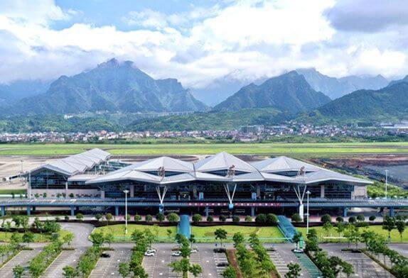
Figure 1 terminal building
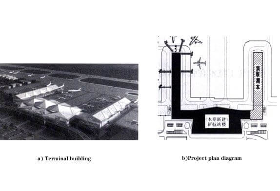
Figure 2 airport building plan
1) The roof is a multi-polyline and multi-slope welded spherical space frame structure, with multiple edges and corners, and the shape is complex;
2) The building is a double-layer structure, with three floors in part, and a room within the mezzanine. The space frame installation working surface is carried out on the second floor, but the crane and transport vehicle cannot go up the floor, and the construction machinery cannot be used for the floor operation, so the construction efficiency is low;
3) The size of the column net is relatively large, including 45mX48m, 45mX29.5m, 45mX29m, 48mX21m, 36mX32m, etc.;
4) The number of space frame components is large, but the number of components with the same specification and length is very small. There are 764 kinds of poles in the terminal building and 6,427 kinds in the main building. Finding poles on site requires a lot of work time;
5) All welding balls, welding workload is large, and all construction is concentrated in the winter rain period, need to take anti-wind, anti-rain, and anti-freezing measures;
6) The normal construction period is severely compressed, and the construction period spans the Spring Festival, so the normal flow operation procedure cannot be adopted.
Due to the tight construction period of this project, in order to provide working surfaces for other professional constructions on the site as early as possible during the roof construction process, the main building and the terminal building must be constructed at the same time. Taking into account that the height of the terminal building is lower than that of the main building and the existing construction equipment of the installation unit, the terminal building adopts the in-situ jacking method of pieces, the main building adopts the in-situ lifting method of pieces, and the cantilever parts are all made of triangular units. Assemble for construction.
The above two construction methods have the following advantages: ①The assembly and welding of the space frame can be basically carried out on the existing floor that has been constructed, reducing the frequency and workload of high-altitude welding operations;②The characteristics of the large slope of the space frame can be used, The layered cross operation method is adopted. The components are assembled on the first layer and welded on the second layer. According to the welding progress, the surface of the components can be treated with anti-corrosion and anti-rust paint on the third layer. The main purlins are constructed on the fourth layer, which can shorten the construction period;③ After the top (lift) of the space frame is raised to a certain height, other professional cross operations can be carried out under the space frame after corresponding protective measures are erected;④ The investment of construction equipment and equipment can be saved. This article only introduces the jacking construction technology of the terminal space frame project.
Since the north-south length of the terminal building is 209m, the space frame is divided into two sections, north and south, for jacking, which reduces the technical requirements and difficulty of jacking. At the same time, the hydraulic jacking device can be recycled to reduce the investment of construction equipment. After the jacking reaches the structural design elevation, the high-altitude supplementary rods between the construction sections are completed to form a whole. The axonometric drawing of the space frame structure is shown in Figure 3, and the construction section is shown in Figure 3.
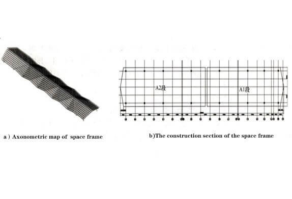
Figure 4 steel structure for the terminal building
5.1 Material transfer
During civil construction, a tower crane is installed at the southwest and northwest corners of the terminal building, which can cover the entire construction work surface. During the construction of the space frame, the tower crane is used to lift the space frame rods and welding balls directly from the material transport vehicle to the 8m floor, and they are tiled according to the installation sequence of the space frame, which saves the on-site secondary transfer time of materials. In addition, since only the space frame material is stacked on the floor, it is conducive to the on-site management of materials and the search for materials in the construction stage. The on-site layout of materials is shown in Figure 8.
5.2 Component assembly and jacking
5.2.1 Stakeout and assembly
This project adopts the in-situ lifting method, and the positioning of the reference space frame is the projection position of the node coordinates of the lower chord.Use the total station for positioning, mark the center line of the node, select the vertical projection center position of several representative spheres, drill a 6mm diameter hole as the reference point, and at the same time as the monitoring point for the vertical deviation control during the jacking process of the space frame .The space frame installation operation surface is the floor, and the flatness is good, which is conducive to the construction line-out and review.Using the control network cable of the civil engineering, accurately lay out the space frame according to the space frame size of the space frame on the floor, and pop up the welding ball to locate the cross line. However, the floor is inevitably uneven, and for the convenience of on-site welding operations and to control deflection For the previous arching operation, the welding ball is raised by 400~600mm as a whole for assembly. The reference space frame node balls of the same plane are kept on the same level, and the level is used to measure at a close distance, so that the unevenness deviation is controlled within 2mm.The space frame assembly starts from the ridge line in the middle; the lower chord space frame is assembled first, followed by the web bar and the upper chord ball to form a stable spatial structure system, and then spread out to the east and west sides along the ridge line.
5.2.2 Work before jacking
Before jacking, the jacking machine should be checked, such as whether there is a crack in the jacking bracket connection buckle and whether the rod is bent; Hydraulic cylinder oil pump and circuit system is normal; The central control system is normal, and the circuit is stable, the hydraulic pump station is normal, etc.Check whether the jacking bracket is tightly combined with the lower string ball node of the space frame and whether the connection part is loose, etc. In addition, before the equipment is officially lifted, it must be tested whether it is working normally with no-load and on-load.
5.2.3 Pre-jacking
First, lift the space frame by about 20mm, conduct a comprehensive inspection of the space frame rods and jacking brackets, mainly check the force of the space frame side rods, whether there is bending instability and depression, etc., and make records in time. If there is an unstable rod, it should be reinforced; check whether the weld is cracked or fallen off, if there is any abnormality, it should be repaired in time according to the relevant welding process requirements before continuing to lift.
5.2.4 Formal Jacking
After the initial jacking reaches a height of 1m, the perpendicularity of the jack and the relative position between the space frame and the axis are corrected. In formal jacking, each operation height is 100mm as a unit of vertical jacking. In order to enhance the overall stability between the jacking frames, when the net frame is jacked up to a height of 6m, a 21.5-inch cable wind rope is drawn between the jacking frames. When the space frame is jacked up to the structural design level, after verifying the coordinates of the key control points, lock the jacking system equipment, maintain the aerial posture of the space frame, install the support diagonal struts in multiple groups, and make the space frame structure form a whole stable stress system as soon as possible.
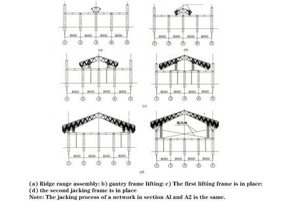
Figure 4 Schematic diagram of the jacking process of the space frame
5.2.5 Construction monitoring and correction
During the lifting process of the space frame, the synchronization, deviation correction and correction should be strengthened. The jacks used for lifting must be lifted synchronously to maintain the level of the space frame. The allowable difference of each jacking point is 1/400 of the jacking spacing, and should not be greater than 30mm, otherwise it will cause changes in the internal force of the space frame members and the axial pressure of the jacking frame. When the space frame is lifted to the design elevation, according to the distance between the space frame support ball and the support, the manual hoist is used to adjust the plane of the space frame, so that the coordinates of the support meet the design requirements.
5.2.6 High-altitude supplementary rod
After the north and south sections of the space frame are jacked up to the design elevation, one row of upper and lower chords and webs are left between the sections, and the construction method of high-altitude supplementary rods is used. The rods with a smaller height from the floor are lifted by ropes, and the rods in the ridge area are lifted in place with a hoist.
5.2.7 Unloading and lifting frame removal
The unloading of the space frame should be carried out in a reasonable order to avoid the uneven force of the rods in the support area after unloading, which will cause the bending and torsional buckling of the components and the overall instability of the space frame or the deviation of the position. After the diagonal struts of the space frame support are installed in place, the lifting frame can be unloaded. Unloading is carried out in 3 steps. The first drop height of the jacking bracket should not exceed 5mm, and the pause time should not be less than 3min. If there is abnormal noise, the unloading should be stopped and the cause should be identified; The height of the second drop should not exceed 10mm, the pause time should not be less than 1min; the third drop should not exceed 15mm. When the cumulative amount of descending height reaches 30mm, the unloading of the jacking frame is basically completed, and then the standard sections of the support are removed in sequence from top to bottom.
Copyright © Xuzhou LF Engineering & Construction Co., Ltd. All Rights Reserved.

 +86-17751936871
 +86-516-8595-0258


