

+86 177 5193 6871
222, Block B, Diamond International, Guozhuang Road, Xuzhou, Jiangsu, China
1. Comprehensive Steel Gymnasium Roof Project Overview
The foundation and main body of the project is a frame shear wall structure, with two floors underground and two floors above ground, with a building area of 35248m². The roof system is an overall shape parabolic hyperboloid arc bolt ball steel space frame structure with a space frame area of 6600m2 and the highest point distance of the roof 35m away from the ground.
2 Engineering characteristics and difficulty analysis
2.1 Complex environment
The project is located inside the school, the environment is complex, the construction site is narrow, and the installation and construction of the steel space frame do not have the use of large-scale hoisting equipment, resulting in the construction of the steel space frame project more difficult.
2.2 Complex shape and large span
The roof steel space frame has a large span, unique shape, and complex structure. The space frame is in the shape of a hyperbolic paraboloid reticulated shell, and the elevation of the column top is complex and changeable, making the construction difficult.
3 Comparison and selection of steel space frame structure construction schemes
The commonly used construction methods for steel space frames include the full scaffolding high-altitude bulk method, high-altitude slip method, block installation method, high-altitude docking method, overall lifting method, and high-altitude bulk method. In view of the actual situation of the project, combined with the commonly used construction methods of the steel space frame, in line with the principles of the scientific and reasonable plan, advanced and feasible technology, concise and applicable process, effective measures, and economical and practical, in order to ensure the quality, progress and safety of the project, 5 construction methods were analyzed, compared and summarized. According to the characteristics and application types of these five construction methods, taking into account factors such as quality, safety, construction period, cost, and construction difficulty, and taking advantage of the advantages and disadvantages of the five construction methods, finally, this project decided to adopt a new construction method. That is, the strip support cantilever expansion assembly method. The characteristics of steel space frame construction are:
(1)It is suitable for the installation and construction of various large-span and complex-shaped steel space frame roof structure systems, and it does not require large construction machinery, and the operation is relatively simple;
(2)During construction, only a small amount of supporting scaffolding needs to be erected, thereby greatly improving Improve labor efficiency and reducing labor intensity;
(3)It can improve work efficiency, shorten the construction period, reduce construction costs and save resources.
4 The key construction technology of steel space frame cantilever expansion and assembly
4.1 Construction situation
During the construction of the space frame structure, only the strip steel scaffolding with a length of 72m and a width of 9m was used in the middle part to be supported between the 1-6 axis and the 1-8 axis, and the floor-type fastener full-hall steel tube scaffold was set up from the elevation of -0∙3m as the support platform for the installation of the starting unit of the steel space frame. The erection height is 25cm lower than the lower string ball of the space frame. The horizontal spacing or row spacing is 1∙2m; the vertical spacing is 1∙5m; the step distance is 1∙8m; the length of the stand extending from the upper end of the pole is 0∙1m; the height of the stand is 20m; the steel pipe used is Φ48×3∙5mm. The rest adopt the technology of cantilever expansion and assembly.
4.2 Space frame cantilever assembly process
Step 1: Set up the starting unit bar support frame. Combined with the engineering structure form and actual construction characteristics, between the 1-6 axis and the 1-8 axis, from the 4.3m elevations, a floor-type fastener-type strip steel pipe scaffold is erected as the supporting tire frame for the installation of the steel space frame structure ( The specific location is shown in Figure 1), and the height should be 20 ~ 30cm lower than the chord ball of the space frame.
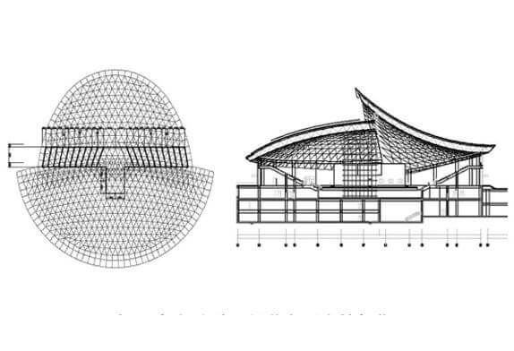
FIG. 1 Position diagram of assembling strip support frame for space frame starting unit
The second step: high-altitude scattered mesh shell starting unit. Using the operating platform that has been set up, lift the loose parts or small assembled units assembled on the ground to a high altitude, and assemble them from the supports at both ends to the middle to form the starting unit of the mesh shell. After checking, it is welded with the supports. To form a stable structural system sufficient to withstand self-weight and construction loads. The assembly of the space frame starting unit is shown in Figure 3. After the starting unit is assembled and the support is welded and fixed, the reticulated shell starting unit can be unloaded, and the strip support frame can be removed.
The third step: the extension and assembly of the space frame cantilever. On the basis of the reticulated shell starting unit assembled in the previous step, the loose parts or the small assembled unit assembled on the ground are hoisted to a high altitude, and cantilevered and assembled symmetrically from the middle to both sides. The sequence is: extend a space frame forward. Along the B~H axis, first install the lower string of the space frame, and then assemble the unit nodes on the ground. Each unit node should be made of one steel ball and four rods; use a hoist or tower crane to hoist the unit nodes to the air. The installation worker sits on the node, and after the high-strength bolts are aligned with the screw holes on the bolt ball, they are tightened, that is, the installation of a unit node is completed, and the installation sequence is extended until the whole axis is installed, and the two ends of the support is temporarily fixed. In order to facilitate the overall adjustment after all the reticulated shells are installed, the support is not welded and fixed at this time.
Step 4: Continue to install it progressively to the next axis by the method of Step 3 until the entire space frame is assembled, and finally install the arches on both sides in place. The cantilever expansion and assembly of the space frame and the cross-section of the space frame after the assembly is completed are shown in Figure 2 respectively.

FIG. 2 a(Assembling sequence diagram of space frame starter unit) and b(Sequence diagram of cantilever expansion of space frame)
4.3 Application effect.
By adopting the space frame cantilever expansion and assembling technology, the number of space frame supports is reduced, the cost is reduced, the construction speed is accelerated, the construction period is shortened by 1 month, and the installation accuracy and the construction of the entire steel space frame roof are improved.
5 Conclusion
This project is a typical complex hyperbolic paraboloid large-span steel space frame structure, which is difficult to construct. After our careful organization and construction, after the completion of the main structure of the project, after testing: the quality of each sub-item project has reached the standard, and has accumulated rich experience in construction, and provided many useful references for the construction of similar projects.
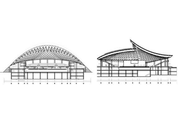
FIG. 3 Section of the space frame after assembly
Copyright © Xuzhou LF Engineering & Construction Co., Ltd. All Rights Reserved.

 +86-17751936871
 +86-516-8595-0258


