

+86 177 5198 6706
222, Block B, Diamond International, Guozhuang Road, Xuzhou, Jiangsu, China
1. Project overview
Roof steel structure system
The steel structure of the project roof is composed of a single-layer reticulated shell (stadium, big tree square and other public areas), a double-layer curved space frame (gymnasium and swimming pool) and vertical support members, as shown in Figure 1.

FIG.1 Top view of the steel structure roof of the sports center
The single-layer reticulated shell is a space-curved reticulated shell structure with a plane length of 532.7m and a width of 240.4m. The maximum height relative to the landing point is 42.3m (the landing point elevation +6.000m). The entire roof reticulated shell is directly “woven” into a quadrilateral space frame by box-section members. Except for the big tree square, the overall dimensions of the space frame members are uniformly 700 × 450 rectangular cross-sections, and the average side length of the space frame is about 4050mm. The opening range of the stadium is 191.2m long and 147.4m wide. The maximum cantilever span of the reticulated shell is 38.71m (the horizontal projection size from the first-level bifurcation point of the tree-shaped column), which is located on the west side of the stadium (Position A in Figure 1). The diameter of the center of the Dashu Square at the landing point is 20.6m, and the rhombus space frame is woven in the shape of a flower basket. The dimensions of the rectangular section members are 400 × 300 ~ 500 × 350, which are naturally connected to the roof space frame. The average side length of the space frame is 1550mm. Due to the complexity of the surface and the generation mechanism of the mesh, all rectangular box-section members have different degrees of spatial bending and twisting characteristics (Fig. 2).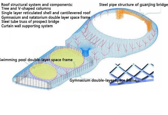
FIG.2 3D view of the overall steel structure
The roofs of the two pavilions are double-layer space frames, which are orthogonally inclined quadrangular pyramid space frames in the form of curved surfaces. The plane projections are all oval. The short axis of the gymnasium ellipse is 104.3m, the long axis is 116.9m, the short axis of the swimming pool is 77.6m, the long axis is 98.6m, and the height of the space frame is 4.5m and 3.5m respectively. The space frame is connected with the single-layer lattice shell through the upper chord ring beam.
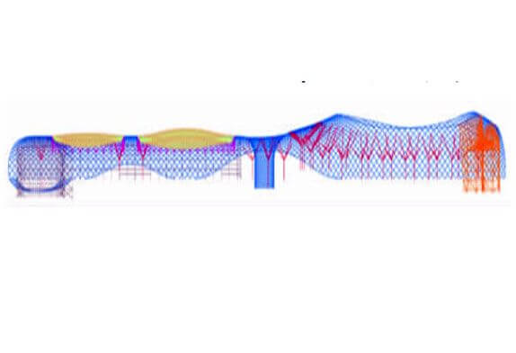 FIG. 3 Overall steel structure elevation
The vertical support system consists of four parts, which are: (1) 31 four-branched tree-shaped columns support the reticulated shell, of which 8 tree-shaped columns on the west side of the stadium are 1500 concrete-filled steel tubular columns. The branches are 900 steel pipes, the trunk of the tree-shaped columns in the remaining positions is 600 4 steel pipe columns, and the branches are 600 steel pipes. (2) The V-shaped columns supporting the space frame and the space frame shell (located under the upper chord beam of the space frame), of which 40 are distributed around the gymnasium and 30 are distributed around the swimming pool. (3) Pylon columns on both sides of the viewing bridge with a clear span of 100m. (4) Curtain wall columns on the west facade of the sunken square. The viewing bridge uses a truss structure (flat arch, corresponding to the upper chord reticulated shell), and the upper and lower chords are connected by V-shaped webs. The clear span of the bridge is 102.8-107.3m, the minimum height of the truss is 11.2m, and the maximum height of the lower chord from the ground is 30.4m. In addition to the above-mentioned support system, the single-layer reticulated shell has a total of 125 floors of supports in the surrounding area and in the Dashu Square, including 38 in the Dashu Square and 87 in the rest. The surrounding of the gymnasium and swimming pool are supported by annularly arranged hollow truss columns to form the envelope system of the glass curtain wall, as shown in Figures 1 and 2.
The spacing between the curtain wall columns is 8.4m. Except for the curtain wall columns on the west facade of the sunken square, the tops of the other truss columns and columns are connected to the reticulated shell through the oblong hole pins (only horizontal loads are transmitted). The curtain wall columns are connected by horizontal cables with a vertical spacing of 6m. At the same time, horizontal connecting beams are set at the corners of the curtain wall and on both sides of the deformation joints. The horizontal connecting beam and the truss column form a stable system to bear the tensile force of the horizontal cable.
The above four vertical members and the landing points on the north and south sides of the reticulated shell together support the overall roof.
2. Structural characteristics and design difficulties
(1) The scale of the overall structure is large, and the local cantilever of the reticulated shell is large. Since the scale of the structure is large in both directions, it is inevitable that the effect of temperature will play a major role in the design of the structure. The maximum cantilever span of the reticulated shell around the stadium is about 38.71m, and the external rigidity of the reticulated shell is small, resulting in a large downward (constant, wind pressure) and upward (wind suction) displacement at this place, which becomes the key locations in the design of the entire reticulated shell.
(2) A large number of single-layer reticulated shells with box-shaped torsional members are quadrilateral space frame structures generated based on complex curved surfaces because all the reticulated shell members are rectangular box-shaped sections. In order to ensure that the center line of the component is located in the curved surface, and the cross-sectional direction of the component is perpendicular to the curved surface, most of the components become torsion components, that is, the component is twisted while bending, which brings great challenges to the design, processing, and installation of the component. great difficulties and challenges.
(3) There are many types of supports, and 31 tree-shaped columns are used to support the reticulated shell to reduce the span of the reticulated shell. The upper string of the space frame of the gymnasium and swimming pool is connected with the space frame shell, and the V-shaped column around the circumference is used to support the space frame and the space frame shell. The sunken plaza curtain wall column is used to support the reticulated shell on it, and the lattice shell acts as lateral support for the curtain wall column. A truss-type viewing bridge is used, and the upper chord is acted by a reticulated shell member. The whole structure is connected with each other through the reticulated shell, and the force is complex.
(4) The viewing bridge has a large span and low stiffness and needs to be designed for comfort. The architectural scale of the viewing bridge determines that the structural stiffness is not large, and the natural vibration frequency is low (1.65Hz), which is relatively close to the pedestrian frequency (1.5-2.5Hz). , under the excitation of pedestrians, it may cause a large vibration of the bridge, resulting in the discomfort of pedestrians. Therefore, it should be evaluated for its comfort under the action of pedestrian excitation, and if necessary, appropriate vibration reduction measures should be taken to improve the comfort of the viewing bridge. In addition, due to the large span of the viewing bridge and the flat arch shape, a large lateral thrust is formed on the bridge tower, which also brings certain difficulties to the design of the viewing bridge.
(5) There are many types of nodes, and the design of key nodes is complicated. Due to the complexity of the overall structure, there are more than a dozen types of nodes in the steel structure of the sports center. The main types of nodes include reticulated shell nodes, reticulated shell landing nodes, tree-shaped columns Column base nodes, bifurcation nodes, branch and reticulated shell connection nodes, V-shaped column base nodes, and column top nodes, viewing bridge and reticulated shell connection node, etc. For some key nodes, due to a large number of intersecting members, the complex spatial relationship between the members, and the large stress on the nodes, the design of the nodes is very difficult.
3. Roof single-layer reticulated shell
The adjustable contents of the roof reticulated shell include: setting additional components, increasing the section of local components, and reducing the overhang span. The adjustment of the reticulated shell is largely limited by the architectural effect.
Expand the opening range and reduce the cantilever span. The horizontal projection of the original opening range of the stadium roof reticulated shell is an ellipse with a long axis of 191.215m and a short axis of 137.537m. In order to further reduce the deformation of the cantilevered end of the reticulated shell, the most direct and effective method is to expand the opening range of the reticulated shell on the roof and reduce the maximum overhang span of the reticulated shell on the west side of the stadium. The new reticulated shell boundary projection is formed by connecting a circle with a radius of 105.0m tangent to the original ellipse boundary (as shown in Figure 9). After adjustment, the maximum cantilever span of the reticulated shell is reduced from the original 48.561m to 38.710m. The pick span is reduced by 9.851m. This solution not only solves the problem of large structural deformation, but also saves a certain amount of steel, and has little impact on the architectural effect, ensuring that the dimensions of the components are uniform and unanimously agreed by the owner and the architect.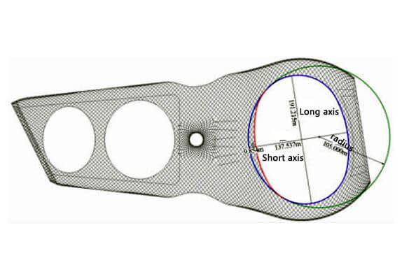
FIG. 4 Expanded opening of stadium shell structure
4. Gymnasium and swimming pool
The gymnasium and the swimming pool are the two indoor venues of the sports center. Due to the needs of large-space building functions, if the roof structure adopts a single-layer reticulated shell like other areas, it cannot span the space of the two venues only by the surrounding vertical support system. It is not possible to set up tree-shaped columns in the stadium like other areas, so the gymnasium and swimming pool must adopt other more reasonable structural forms.
In the design, regarding the structural form of the two venues, three schemes of fish-belly structure, truss structure, and space frame structure are mainly considered. In order to ensure the unity of architectural style, the gymnasium and the swimming pool adopt the same structural form in the design, but the specific structural parameters are different due to the different plane scales of the two.
(1) Fish belly structure scheme
The scheme structure is an orthogonal half-open fish-belly truss structure, the upper chord is a rectangular steel pipe, the lower chord is H-shaped steel, and the web is a round steel pipe. Its typical features are two-way orthogonal; semi-empty; fish-bellied shape. The two-way orthogonality is to be consistent with the arrangement of the surrounding single-layer reticulated shells; the semi-empty web means that only 1 to 2 internodes near the end of the truss are provided with inclined webs, while in the middle internodes, only vertical webs are provided Rod, no oblique belly rod. The arrangement of the structural sloping web bars follows the distribution law of shear force, so as to achieve the purpose of effectively transmitting shear force; while the height of the fish-belly truss follows the change law of the bending moment, the section at the maximum bending moment is the highest, and the resistance to the bending moment is the highest. The ability is also the greatest. Orthogonally distributed trusses effectively solve the out-of-plane stability problem of plane trusses. From the perspective of force, although this structure is not a space structure, a combination of two plane structures, the overall force transmission of the structure is clear and simple, with high bearing efficiency and a beautiful architectural appearance.
In the fish-belly truss scheme designed for the two stadiums, the maximum height of the truss of the swimming pool is 8.66m, the maximum height of the truss of the gymnasium is 11.70m, and the distance between the trusses is about 12m (corresponding to the three basic space frame of the surrounding reticulated shell). Between the fish-belly trusses, corresponding to the component arrangement of the surrounding reticulated shells, a single-layer structure formed by “well”-shaped secondary beams is set on the upper and lower chord surfaces of the trusses, thereby forming a primary and secondary structure system with very clear stress.
(2) Truss structure scheme
The truss scheme is a parallel chord orthogonal truss structure, that is, the height of the truss remains unchanged, and the upper and lower chords are in a plane equidistant offset relationship. The height of the truss is determined according to 1/20 of the short span of the stadium plane projection, of which the height of the truss of the swimming pool is 3.8m, and the height of the truss of the gymnasium is 5.0m. Similar to the fish belly structure, the roof structure in the form of orthogonal trusses is also a primary and secondary structure stress system. The layout of the main truss and the form of the secondary structure is exactly the same as the fish belly structure scheme.
3) Space frame structure scheme
The space frame structure is divided into many forms according to the different layout forms and force mechanisms. The space frame structure designed by the project is an inverted quadrangular pyramid space frame structure that is placed orthogonally and obliquely. Different from the first two schemes, this form of space frame is a typical spatial structure, and the overall force does not have a primary and secondary relationship, as shown in Figure 10. The height of the space frame is determined according to 1/20 to 1/25 of the short span of the stadium plane projection, specifically, the height of the swimming pool is 3.5m, and the height of the gymnasium is 4.5m.
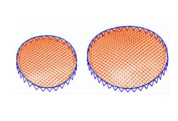
FIG. 5 Space frame structure scheme
The comparison of the three structural schemes is shown in Table 1. The structural efficiency in the table refers to the ratio of the structural bearing capacity to the amount of steel used. Under the same bearing capacity, the smaller the amount of steel used, the higher the efficiency of the structure. According to the calculation results, the steel consumption of the space frame structure is the smallest, the steel consumption of the truss is the largest, which is about 1.72 times that of the space frame structure, and the second is the fish belly structure, which is about 1.35 times that of the space frame structure. From the construction point of view, the space frame has the highest construction complexity due to the largest number of rods, followed by the truss structure, and the construction of the fish belly structure is the most convenient. Corresponding to the construction complexity, a structure with more rods will have a poorer appearance without the exterior decoration of the building.
Table 1 Structural scheme comparison of the two solutions
|
Structural solution |
Structural efficiency |
Construction complexity |
Building appearance |
|
Building appearance |
Medium |
High |
Good |
|
Truss structure |
Low |
Medium |
Medium |
|
Space frame structure |
High |
Medium |
Poor |
From the comparison in Table 1, the truss structure is obviously the least desirable solution, while the fish-belly structure is a more reasonable choice. However, the equipment major needs to arrange a large number of fans and supply and return air pipes within the height of the roof structure, and the fish-belly structure is closed into a line at the roof boundary of the venue, and there is no internal space to use. The equipment pipes are installed under the structure at this position, so that Completely destroys the overall effect of the fish belly structure. For the construction profession, other measures cannot make up for the damage caused by the equipment pipeline.
Due to the uncertainty of future use, the suspension requirements of stadium concerts and NBA games, etc., the roof structure of the gymnasium and swimming pool finally gave up the seemingly reasonable fish-belly structure plan, and chose the space frame structure as the implementation plan, leave more room for future use.
Copyright © Xuzhou LF Engineering & Construction Co., Ltd. All Rights Reserved.

 +86-17751936871
 +86-516-8595-0258


