

+86 177 5193 6871
222, Block B, Diamond International, Guozhuang Road, Xuzhou, Jiangsu, China
1. Airport terminal construction project overview
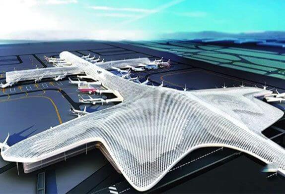
The construction area of the airport terminal building is 451,000 m². The steel roof of the airport terminal construction adopts a double-layer diamond mesh tube truss welded ball joint space frame. The steel space frame and truss components are mainly made of Q345B; The steel plate materials are Q345C, Q345GJC, the maximum plate thickness is 160mm; the cast steel materials are all G20Mn5; the pins are made of 45# steel and Q345C, and the bearing material is 40Cr.
The airport building roof of the hall is a free-form surface, with a length of about 640m from east to west and a width of about 324m from north to south. The support structure consists of tapered pipe columns, core tubes, and arched reinforced trusses in the transition area. The fulcrum spacing is 36m. The main truss is arranged between adjacent fulcrums along the axis direction and is connected with the chord of the space frame in an oblique direction. The upper end of the inverted conical steel pipe column is rigidly connected to the main truss, and the lower end is hinged to the concrete embedded part, forming a frame structure with the main truss, which is the main lateral force resistance system of the roof structure.
The cross corridor area is about 750m long from north to south and about 640m wide from east to west. Most of them are regular cylindrical shells, supported on reinforced trusses with a spacing of 18m. The standard span of the trusses is 45m and the maximum span is 67m. The reinforced trusses with larger spans in the cross corridor area are provided with V-shaped support columns and horizontal steel tie rods, and in the transition area of the corridor hall, the reinforced trusses are provided with rocking column supports(see Figures 1 and 2).

FIG. 1 Airport building roof structure plan
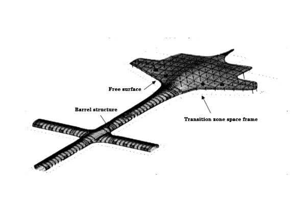
FIG. 2 Perspective of the airport terminal roof structure
2. airport terminal construction deployment
2.1 Main construction methods
The reinforced trusses in the corridor area are assembled on the ground in sections, supported by point-type tire frames, and hoisted in sections outside the span of large crawler cranes.
The steel columns and main truss of the central hall are installed on the 4th floor with 4 traveling tower cranes, and the roof space frame in the external area is installed with 2 250t crawler cranes. According to the structural characteristics and on-site construction conditions, the roof space frame adopts the unit hoisting method, the block hoisting method, and the high-altitude bulk installation method.
2.2.Airport building construction zoning and sequence
On the whole, the on-site steel structure construction is divided into two areas: hall (area A) and corridor (area B) with the axis as the boundary. Generally speaking, the construction is carried out from north to south in the order of the corridor first and then the hall (see Figure 3).
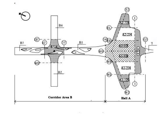
FIG. 3 Airport building construction plane zoning
2.3 Main hoisting equipment
According to the segmental quality and installation progress of the corridor reinforcement truss, 2 sets of 300t crawler cranes and 4 sets of 260t crawler cranes are selected as the main lifting equipment, and 4 sets of 150t crawler cranes are additionally equipped to hoist the side elevation space frames and re-installation times Purlins, horse tracks and other components. The hall is equipped with 4 sets of D1100 walking tower cranes. The track is set on the 4th floor of the hall on the concrete floor, along the four axes of WB, WH, EB and EH, and the track adopts an H-shaped steel beam. In addition, it is equipped with two 260t crawler cranes, responsible for the hoisting of surrounding steel columns and cantilever space frames.
3. Airport terminal installation methods
3.1 Corridor steel structure installation
(1) The construction method means that the gallery area is a cylindrical shell structure, and its reinforcing trusses are assembled on the ground in sections, supported by point-type tire frames, and hoisted by crawler cranes across the outside; Block assembly, crawler crane hoisting, and high-altitude scattered assembly of scaffolding.
2) Terminal building Construction process
During the civil construction of the 8.6m concrete structure, the pre-embedding of the track embedded parts of the skid frame shall be carried out simultaneously. After the civil construction of the 8.6m concrete structure is completed, the installation of the steel structure of corridor B area begins, B1, B2, B3, and B4 are unfolded in sequence according to the civil construction sequence. After the installation of the B2 and B4 areas is completed, the construction of the cross corridor area of the B5 area begins.
3.1.1 Support installation
After the concrete special-shaped column is poured, check the installation accuracy of the embedded parts at the top of the column, and measure the center line of the support and the positioning line of the support ear plate on the embedded plate. Install the support lug welding pad along the positioning line. After the cast steel support is assembled with the joint bearing, pin shaft, and support lug plate on site, it is hoisted into place by a truck crane, and the support lug plate and the backing plate pre-welded on the embedded part are fixed by positioning welding.
3.1.2 Reinforcement truss installation
There are 71 reinforced trusses, with a standard span of 45m and a maximum span of 99m. Due to the high cross-section, only the method of bulk transportation and on-site assembly can be adopted. According to the span of the truss, the 4 reinforced trusses are divided into 6 sections, and the remaining 67 reinforced trusses are divided into 4 sections, and the maximum section weight is 67t. The reinforcing truss is divided into two parts from the middle of the span, and the ground on both sides of the structure is assembled horizontally. The assembly site is leveled in advance, and the assembly racks are set. First, place a rectangular chord on the assembled tire frame, set out through CAD, and take out the positioning coordinates of the four corner points of the segmented interface. The positioning coordinates of the connection port between the truss root and the cast steel support are the key points of control. In addition, take the distance dimension between the four adjacent nodes of the upper and lower chords at several places, the selected control dimension forms an X-shaped cross-slash, measure the positioning coordinates and mutual distances of each control point with a total station, and adjust the chord Positioning to the optimal position to eliminate production errors. The corrected chord is fixed with a horse plate and a tire frame, and then the node center of the truss web is measured and placed on the chord web, and an ink line is marked along the web direction. The web rods are positioned and installed according to the intersecting sequence and marked with ink lines to ensure the welding of the concealed welds at the intersecting mouths (see Figure 3).
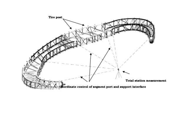
FIG. 3 Schematic diagram of the ground assembly of the reinforced truss in the depression area
3.1.3 space fame installation
The space fame is divided into the top surface and two side elevations for ground assembly to reduce the erection height of the assembled tire frame and the operation frame. The top space fame has a larger installation radius and is hoisted by a 260t crawler crane, and the side elevation space fame is hoisted by a truck crane. The basic assembly unit of space fame is a rhombus space fame structure. When the top space fame frame is assembled on the ground, it is assembled into pieces according to the installation posture, and the internal components of each unit are welded and fixed; after the sliding tire frame is in place, the control axis and elevation of the floor are measured to the top of the tire frame, and the top support of the tire frame is adjusted. The elevation and axis of the support until the design configuration requirements are met. Then use a crawler crane to hoist the assembled unit to the skid-steering tire frame. The rods on both sides of the space fame-frame assembly unit are connected to the reinforcing truss rectangular chords. It is difficult to install with high-altitude parts to ensure that the angle of the intersecting port and the gap of the weld meets the requirements of the specification. The side façade space fame is set out by CAD, and the structure is laid down to the flat assembly posture as possible to obtain assembly coordinates. Before the network frame is assembled, erect the scaffolding for assembly, lay the scaffolding board, and then measure and place the ball joint to support the D180 steel pipe until the steel pipe support meets the requirements of the center coordinate positioning of the ball joint. Hoist the ball joints, and then assemble the space fame members. Assemble and weld the space fame frame to remove the scaffolding, set up a supporting tire frame on the ground outside the space fame frame on the side elevation, demould the space fame frame with a crane and place it on the ground of the installation area, replace the sling, and use the inverted chain on the sling to adjust To determine the posture of the space fame, hoist the space fame to the supporting tire frame, select the measurement and control coordinates of some spherical nodes, adjust the posture of the space fame to meet the design requirements, then temporarily fix the hoisting unit, and install the components between the space frame and the reinforcing truss (see Figure 4)
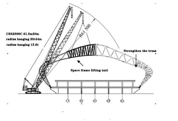 FIG. 4 Analysis of the hoisting conditions of the space frame
3.1.4 Slipping racks
For areas B2 to B4 of the corridor, each area is equipped with a set of slipping racks. After the construction of the B3 area is completed, the racks will be slid to the north of the 29th axis of the B1 area for construction, and the south of the 28th axis will be installed with a point-type rack.
3.1.5 Structural unloading
The steel structure of the corridor is unloaded in stages with the installation progress. Before the racks slide, unload the space fame first, adopt the method of dismantling the support points at intervals, remove the space fame fulcrum points in the span 2 times, and then unload the reinforcing truss, set 6 unloading points for each truss, and use jacks as points Steps for small displacement unloading.
3.2 Hall steel structure installation
1) Construction method
The civil structure of the hall has 4 floors and part of it is 5 floors. Four large walking tower cranes are installed on the 4th floor, and the construction is advanced from north to south to meet the hoisting of steel columns, reinforced trusses, and space frames in the hall. In addition, 6 sets of 8t truck-mounted cranes are arranged to assemble the space frame on the 4th floor, and the surrounding cantilever space frame is assembled on the ground nearby, and then hoisted by 2 sets of 260t crawler cranes. Some space frames are lifted by a winch. The space frames with smaller net heights, such as the regional space frames corresponding to the 5th floor, shall be supported by full-floor scaffolding and shall be bulk-packed at high altitudes (see Figure 11).
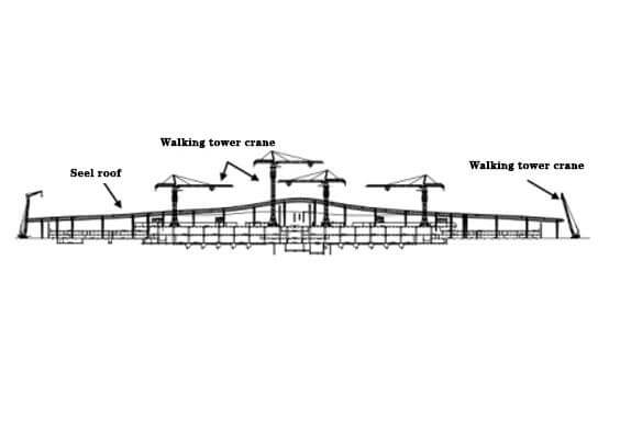
FIG. 5 The layout section of the tower crane in the steel structure construction of the hall
After the handover of the civil work surface in the construction process of the hall, the 260t crawler crane will first install the middle walking tower cranes No. 1 and No. 2. After the tower crane installation is completed, the A1-1/A2-1 steel structure construction will be started; then the 260t crawler crane will be installed. The crawler cranes are then installed on both sides of the No. 3 and 4 walking tower cranes, and then start the installation of A1-2 and A2-2, and the crawler cranes start the construction of areas A1-3 and A2-3 simultaneously. In general, the installation direction of the A1 and A2 areas is to advance the construction from the 13 axes to the 1 axis along the track direction.
3.2.1 Main Truss Installation
The two ends of the main truss are connected with the cross stiffening plate at the top of the vertebral column by pin shafts, and the matching clearance between the pin shaft and the ear hole is 2mm. Connected together, the main truss is hoisted after the floor is horizontally spliced, and the oblique web bars at both ends of the main truss are left at a high altitude for re-installation. The truss is hoisted at 4 points, and the hoisting point is set at the upper chord node. After the upper and lower chords of the truss are connected to the column top insert plate, the coordinates of the truss node are measured with a total station, and the truss is adjusted to meet the accuracy requirements immediately after it is fixed by positioning welding Insert the welding seam of the plate, and then install the end inclined rod.
3.2.2 Space frame installation
The steel structure of the hall is hoisted by 4 traveling tower cranes and 2 260t crawler cranes. The tower crane is mainly responsible for the installation of the roof and its supporting structure in the middle of the hall, and the 260t crawler crane is mainly responsible for the installation of the steel structures on both sides of the hall.
1) Ground assembly, high-altitude hoisting
According to the form of the space frame, the site conditions, the lifting capacity of the hoisting equipment, the cantilevered space frame around the hall, the facade space frame of the corridor, and the transition area of the hall adopt the construction technology of ground assembly and overall hoisting. The space frame hoisting unit is divided according to the lifting capacity of the equipment, the coordinates are converted before assembly, the installation coordinates are converted into assembly coordinates, and the assembly height is reduced. Set the ball joint support according to the assembly coordinates, hoist the ball joint, align the welded ball stiffener plate with the chord, hoist the chord and the web, and weld and fix the ball joint.
Before the space frame is hoisted, set the support tire frame at the installation position, and the space frame fulcrum of each hoisting unit is ≥3. Adjust the elevation of the fulcrum and the position of the axis to the design requirements. The space frame is hoisted at 4 points. The lifting point is set on the lower string ball node around the geometric center of the single space frame. There are 4 pieces of chain hoists with 5t between them, which can adjust the installation angle of the space frame when lifting. After the mesh frame is hoisted above the tire frame, it is guided by the operator on the tire frame and slowly falls on the set fulcrum. Randomly measure the coordinates of the ball nodes and release the hook after meeting the requirements. The components connected to other units around the hoisting unit are retrofitted.
2) Floor assembly, hoist lifting
The 36m×36m standard unit space frame separated by the main truss in the center of the hall has a maximum installation height of 32m. After the floor is assembled, it is lifted into place by a hoist, and the maximum lifting unit is 68t. The lifting mechanism is 4 groups of lattice-type tire frames and its top connecting truss. The standard sections of the lattice-type tire frame are connected by flanges, and the top of the tire frame is connected with each other by a connecting truss to ensure the stability of the lifting tire frame. The lifting point of the space frame is set at the lower chord node of the space frame, and each lifting unit is set with 4 lifting points, corresponding to the 4 lifting tire frames. The space frame lifting unit is calculated and analyzed, and the structural stress and deformation meet the requirements. The top of the lifting tire frame is an overhanging cantilever triangular truss, and the fixed pulley block at the lifting end is fixed at the outer end of the truss, and its vertical projection point coincides with the lifting point of the space frame (see Figures 5 ).

FIG. 5 Space frame lifting
The steel structure project of the airport terminal is large in scale, complex in shape, and exquisite in detail design, Airport cost to build should be calculated according to the specific project through the comprehensive application of high-altitude parts installation, block hoisting, unit lifting, and other methods, the installation accuracy of the space frame is well guaranteed, safety hazards are reduced, and engineering costs are reduced.
Copyright © Xuzhou LF Engineering & Construction Co., Ltd. All Rights Reserved.

 +86-17751936871
 +86-516-8595-0258


