

+86 177 5193 6871
222, Block B, Diamond International, Guozhuang Road, Xuzhou, Jiangsu, China
The exhibition center consists of Hall 1 of the Convention and Exhibition Center and Conference Center (building area of 16159.90m²), Hall 2 of the Convention and Exhibition Center (building area of 19720.60m²), and supporting garages and other auxiliary facilities. The total construction area is about 37407.10m², and the total installed capacity of steel structures is About 9200t, it consists of about 5000t of the lower beam-column structure and about 4200t of the upper roof structure, and the steel material is Q355B. The steel structure roof is composed of plane tube trusses with a maximum span of 76.5m, which are connected by single trusses. The entire roof trusses are supported on the surrounding frame columns. The height of the project building is 28.4m for Hall 1 and 29.3m for Hall 2.
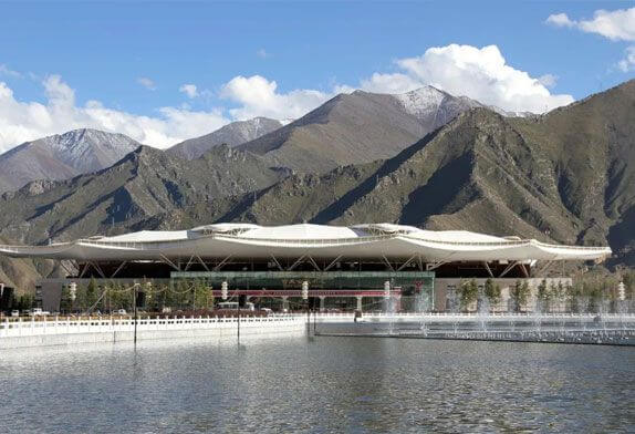
FIG.1 exhibition hall steel structure
1) Located in the Lhasa area with high altitude and low oxygen content, it is difficult to work at high altitudes.
2) The roof is a space-curved tube truss structure with complex shapes and difficult spatial positioning.
3) The temperature difference between day and night is large, which requires high welding quality. The average temperature in Lhasa is low, and the temperature difference between day and night is large. The average maximum temperature from July to October is 17.8-22.8°C, the average minimum temperature is 2.8-10.7°C, and the average temperature difference between day and night is 13° Around C, work measures in large temperature difference environments must be considered.

FIG.2 hall roof design
Taking the roof of Hall 2 of the Tibet Convention and Exhibition Center as an example, the length is 173m, the width is 143m, and the mass is 2200t. According to the characteristics of the roof, when the hydraulic synchronous lifting scheme is adopted, the roof steel structure is divided into the outer roof steel structure part. And the steel structure part of the inner roof, as shown in Figure 2. The outer roof steel structure is installed by combined units, and after the inner roof steel structure is assembled on the ground into a whole, it is lifted into place by hydraulic synchronous lifting technology.
This scheme has the following advantages:
①The main components are assembled on the ground tire frame, which effectively overcomes the difficulties caused by the construction environment of high altitude and low oxygen content, improves the construction efficiency, and is easy to guarantee the construction quality;
②The outer roof’s simultaneous construction with the internal roof can effectively save the construction period and speed up the progress;
③Through the roof zoning, the span and quality of the lifting of the internal roof can be appropriately reduced, which is conducive to the control of roof lifting;
④Temporary measures cost greatly reduce and reduce construction costs;
⑤ Avoid cross-operation with civil works, which is beneficial to on-site construction organizations.
The outer roof is divided into 24 hoisting units for installation. The inner roof is assembled as a whole and then lifted into place. The roof construction process is: assembling and welding the inner and outer trusses of the roof → hoisting the outer roof truss → lifting the inner roof truss → Butt joint, make up after installation → Remove temporary reinforcing rods → Temporary support and unloading of a roof truss.
The outer roof is hoisted by one 400t crawler crane, and two 50t truck cranes are used for reverse transportation of components. In order to balance the quality of the overhanging part of the hoisting unit of the outer roof, according to the actual situation, necessary temporary supports are set on the outside of the lower chord for reinforcement, and the temporary supports are set on the upper part of the surrounding floor deck. The segmented parts of the inner and outer roof trusses must be reinforced because the inclined web rods cannot be pre-installed and cannot form an effective stress system, as shown in Figure 3.
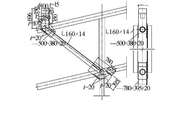
FIG.3 Lifting point reinforcement
At the same time, the lifting part of the internal roof has a large span and mass, resulting in a large vertical deformation, which must be strengthened. Therefore, the auxiliary truss system is added to make the internal roof system and the lower suspended ceiling platform system cooperate with the force, forming a composite truss system and reducing the deformation, as shown in Figure 4.
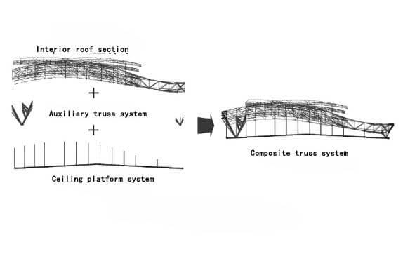
FIG.4 Composite truss system
There are 20 sets of hoisting points and 4 hydraulic lifters in this project. One set of synchronizing sensors is set at each hydraulic lifter to measure the displacement synchronization of each hydraulic lifter during the hoisting process. The arrangement of lifting points is shown in Figure 5. The lifting equipment adopts two kinds of hydraulic lifters, TLJ-600 and TLJ-2000; TLD-60 hydraulic pump source system; TLC-01 computer synchronous control and sensor detection system.
1) The temperature difference of the construction environment is relatively large, with an average temperature difference of about 13°C between day and night, so the operation measures in the environment with a large temperature difference must be considered.
2)The main stress joints are cast steel members, and a reliable welding process must be developed to ensure welding quality.
3) The form of the engineering structure is relatively complex, the joints are intersected with the rods, and the primary and secondary structures influence each other, so the welding sequence should be considered.
The delivery state of the steel castings used in this project is quenched and tempered QT (that is, quenched + tempered), and the steel pipe is made of low-alloy steel Q345C. It is the first case of operation in a construction environment with a large temperature difference, and there is no mature experience for reference. . To this end, according to the “Technical Regulations for Welding of Steel Structures in Buildings” JGJ81-2002, combined with the characteristics of the large temperature difference between day and night, long sunshine time, and large temperature difference between the surface light side and the backlight side, the welding process is evaluated to ensure the quality of the project. The quality grade of the butt weld between the steel casting and the steel pipe of this project is the first grade, and the flaw detection standard shall comply with the “Steel Weld Manual Ultrasonic Flaw Detection Method and Classification of Flaw Detection Results” GB11345-1989, the inspection grade is B grade, and the evaluation grade is II grade. The carbon content of steel castings is 0.18% to 0.20%, and the thickness is 25 to 55mm.
Determine the welding sequence of component assembly, and draw the welding sequence diagram of the components; perform welding in the specified order to reduce stress concentration; part of the roof is assembled into a whole, and the welding expansion section is reserved. After the measurement and correction are qualified, the post-repair rod welding. After the overall lifting is in place, combined with the on-site temperature, the welding time is selected from 11:00 to 17:00 when the temperature change is small, and the welding is carried out from the middle to both sides, so as to avoid structural deformation caused by temperature stress as much as possible.
Copyright © Xuzhou LF Engineering & Construction Co., Ltd. All Rights Reserved.

 +86-17751936871
 +86-516-8595-0258


