

+86 177 5193 6871
222, Block B, Diamond International, Guozhuang Road, Xuzhou, Jiangsu, China
1. Project Overview
This project is located on the northeast side of the built airport terminal in Inner Mongolia. The whole is divided into a new terminal building and a large platform in front of the building. The center of the new terminal building is a large dome with a diameter of 108m, and the wingspan of the two wings of the building is about 500m. The building area is about 100,000 square meters. The total height of the building is 51.7m, and the highest cornice of the dome is 33.7m. The main structure adopts a reinforced concrete frame structure, and the roof adopts a large-span steel structure roof.

Figure 1 Aerial view of the airport building
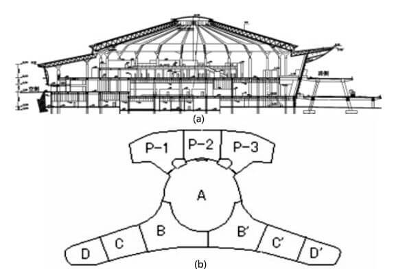
Figure 2 a(Middle Sectional View) and b (Schematic diagram of building joints)
2.1 Main structure design
2.1.1 Structural seam
The total length of the terminal building is about 500m, which is far beyond the requirements of the specification to set the maximum spacing of expansion joints. Method for setting up structural joints (vibration-proof joints and temperature joints). A total of 6 structural joints are set up to form 7 independent structural units.
The large platform is an outdoor building with a total length of about 210m. In order to meet the requirements of the code, the main part of the structure is divided into three independent structural units by using structural joints. After the structural joints are set, the plane size of each independent structural unit is still too long. The following measures are adopted: 1) In order to reduce the influence of the shrinkage and deformation of the concrete, the post-casting belt is appropriately set at the temperature (generally, the length of the structure between the post-casting belts is not equal. more than 45m); 2) Appropriately increase the reinforcement ratio in the parts that are affected by temperature and change greatly, and adopt the method of setting fine and dense temperature reinforcement; 3) Prestress is applied to the frame beam and main secondary beam, and it is arranged in the outdoor large platform slab Longitudinal prestressed tendons; 4) Concrete raw materials, necessary measures during construction, etc.
2.1.2 Selection and design of the main concrete structure
In this project, the reinforced concrete frame structure system is selected according to the comprehensive consideration of the use function, building layout, economy and other factors. The frame column net is about 18mx18m. In order to reduce the self-weight of the structure, reduce the height of the structural members, and reduce the shrinkage deformation caused by the super-long concrete, the main beam and the main secondary beams of the frame adopt the slow-bonding prestressing technology, and the height of the main beam adopts 1000-1300mm, the long-span section adopts well-shaped secondary beams, the size of the well-shaped secondary beams is 700-900mm, and the thickness of the floor slab is 120mm.
The frame column adopts a column with a diameter of 900-1300mm according to the architectural requirements. Cross-shaped steel-concrete columns are used for the frame columns supporting the upper steel structure roof. Large platform: The size of the column net is 20mx20m, and the inclined column and the beam form a frame. The beam and slab selection adopts the reinforced concrete primary and secondary beam floor plan, and the structure is sloped. As the large platform is used as the main outdoor traffic passage of the terminal building, the span is large, the load is large, the dynamic load, and the force is close to the design of the road bridge, so the secondary beams are arranged in one direction, and the prestressing technology is used in the primary and secondary beams to reduce the beam height. , longitudinal prestressing tendons are also arranged in the plate to solve the problem of force and temperature stress. The beam section of the large platform part is 1000×1600 ~ 1700×2000, and the thickness of the prestressed floor slab of the large platform is 250mm.
2.1.3 The connection design of the main concrete structure and the upper steel structure roof
The main concrete structure and the upper steel structure roof are connected by “Y”-shaped steel supports. The central dome is connected by the radial truss of the “Y”-shaped steel support and the upper steel roof, and the connection nodes are cast steel rigid nodes. Hinged support (swivel spherical steel support). The roofs of the boarding halls on both sides are connected with the grid structure of the “Y”-shaped steel support and the upper steel roof. Rigid connection method for columns embedded in concrete columns.
2.1.4 Steel Roof Design of Terminal Building
The upper roof of this project adopts a steel structure to meet the requirements of building use. Corresponding to the lower concrete structure, the entire building steel structure is divided into 7 independent temperature zones. The middle section is a dome with a span of 108m and a steel canopy with a cantilever of 16m at the entrance edge (Area A), which is mainly a space tube truss structure; the surrounding A section is a multi-span space curved grid structure supported by multiple columns (B area), its typical span is about 27m; adjacent to B area are C area and D area, C area and D area are horizontal single-span space curved grid structure, the span is about 27.2m.
The circular dome with a span of 108m in the middle of the terminal building adopts a conical steel roof consisting of 24 radial trusses and a single-layer reticulated shell between the trusses. The radial truss adopts an inverted triangular section, one end of which is supported on the “Y”-shaped steel support column raised from the lower concrete column, and the other end meets the inner ring steel tube truss beam with a diameter of 20m in the middle of the dome. The section of the inner ring steel tube truss girder is 1.7mx2.9m, the upper section of the 24 radial trusses is about 1.7m high, and the lower section is about 2.8m high. The truss joints use intersecting joints or welded ball joints according to different stress parts. , the single-layer reticulated shells between the trusses are connected by cut crown spherical nodes. The canopy at the front end of the dome is in the form of a cantilevered plane truss.
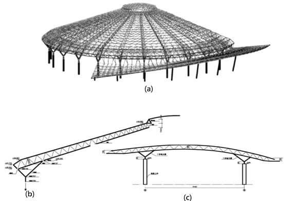
Figure 3 a (A three-dimensional schematic diagram of the dome and canopy) 、b (Section A of the main truss of the dome in Area A) and c (Section C and D area of the space frame)
Copyright © Xuzhou LF Engineering & Construction Co., Ltd. All Rights Reserved.

 +86-17751936871
 +86-516-8595-0258


