

+86 177 5193 6871
222, Block B, Diamond International, Guozhuang Road, Xuzhou, Jiangsu, China
The Expo Center has a total construction area of about 160,000 square meters, including anThe Expo Center has a total construction area of about 160,000 square meters, including an indoor football field of about 30,000 square meters, which can accommodate more than 30,000 spectators. of about 30,000 square meters, which can accommodate more than 30,000 spectators. It is the first indoor football field in my country. The plane size of the roof of the football field is 144×204m (excluding the surrounding podium), with two-way orthogonal and positive venting, inter-truss, and all-steel structure. The roof is supported on a steel frame podium about 40m high, and the roof is made of colored profiled steel plates. The steel structure roof was designed by the Ninth Design and Research Institute of China Shipbuilding Industry, Jiangnan Shipyard undertook the steel structure fabrication, and China Construction Third Engineering Bureau carried out the steel structure installation. The entire roof consumes about 5,000 tons of steel, including 120,000 sets of high-strength bolts and more than 200 tons of welded metal. The structural installation was completed in September 2000. It is currently the steel structure roof with the largest span in China and one of the steel structure roofs with the largest span in the world.

Figure 1 Steel Structure Indoor Football Stadium
The roof structure is supported on 40 steel columns of the surrounding podium, the column spacing is generally 18m, the vertical and horizontal truss spacing is 6m, the lower chord installation elevation is 40m, and the roof structure height is 10m. Among them, the midpoint of the transverse truss (that is, the direction of 144m) arches 3.6m to form a 5% roof slope. The roof structure layout is shown in Figure 2. The trusses directly supported on the steel columns of the podium are the main trusses with a spacing of 18m or 12m. The main truss and the steel column of the podium are connected by basin-type rubber bearings. The secondary trusses are set every 6m between the main trusses, and the secondary trusses are supported on the side trusses arranged along the periphery of the rhinoceros cover. The side trusses are equivalent to continuous 18m-span brackets and adopt a super statically determinate parallel chord truss system with cross-web members. Each stick truss in the entire roof adopts the upward-supporting inclined web bar system to minimize the length of the compression web bar.
A total of three layers of vertical and horizontal supports are arranged on the upper and lower chord planes of the roof and the middle plane at a height of 5m. The setting of the horizontal support of the middle layer can reduce the calculated length of the web member by half.
For long-span trusses, the current steel structure design code requires that the influence of the horizontal thrust generated by the elastic elongation of the lower chord on the supporting members under gravity load be considered during design. According to the span scale of this project, if a horizontal rigid constraint is set at the roof support so that there is no relative displacement between the roof support and the support column top, according to the lateral force stiffness of the support structure, under load, due to The horizontal force generated by the elongation of the bottom chord on the top of the column will exceed 600kN. Such a huge thrust will bring great difficulties to the design of the column, and the horizontal constraint will have a considerable adverse effect on the bottom chord of the end span of the truss. Because the horizontal thrust and the resulting displacement are too large, the flat rubber bearing commonly used in the space frame structure is no longer competent. Because the shear deformation of the flat rubber bearing is far from meeting the requirements of this project, the pressure up to 6000kN is not what this type of bearing can bear. After repeated research, we finally borrowed the practice of bearings in bridge engineering and adopted basin-type rubber bearings. Figure 2 is its schematic diagram. The upper basin of the basin-type rubber bearing is welded to the support plate of the roof, and the lower basin is welded to the steel plate on the corbel surface of the support column. Since the friction coefficient between the stainless steel plate on the bottom of the upper basin and the four-air plate on the top of the lower basin is very small, relative displacement can occur between the upper and lower basins under the action of the horizontal force of the roof, and the horizontal force transmitted from the roof to the supporting structure is only It is just friction so that the horizontal force generated by ordinary bearings is much smaller. At the same time, the rubber block placed in the lower basin is in a three-dimensional stress state under the action of vertical force. At this time, the rubber has a property similar to a fluid, so that relative rotation can occur between the upper and lower basins to meet the support when the roof deforms. seat rotation requirements.
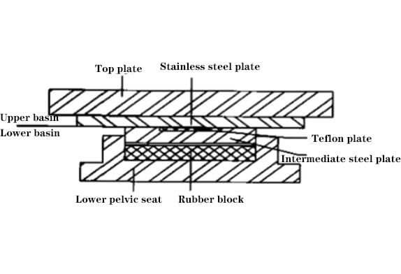
Figure 2 Basin rubber bearing
The upper and lower chord nodes of the entire roof are constructed of welded cross-shaped gusset plates. The transverse truss members are generally connected to the gusset plate by welds, and the longitudinal truss members are generally connected to the gusset plate by high-strength bolts. Figure 3 shows two typical nodes. Compared with the cross-slab joints used in commonly used space frames, the characteristics are as follows: 1) Since the transverse truss is the main direction of force, its upper and lower chords are connected in the joint area to ensure the reliable stress of the main members. The gusset plate is connected to the transverse truss chord by butt welds, and then the web is connected to the gusset plate. 2) The transverse truss is assembled on the ground, and the rods are generally connected by welds in the node area, but the end inclined rods are connected by welds and high-strength bolts in order to reduce the size of the gusset plate due to the large internal force. 3) The longitudinal truss is assembled from high-altitude parts. In order to minimize the high-altitude welds, the chords, and webs are connected to the gusset plates with high-strength bolts. 4) Due to the use of cross-shaped gusset plates, the centroids of the upper and lower chords and vertical bars of the truss basically coincide with the centroids of the connecting welds (or high-strength bolts) on the gusset plate, and the mechanical performance is better, but the oblique web The rod is only connected to the gusset plate by the flange of the T-shaped member, and there is an obvious eccentricity between the centroid of the T-shaped section and the centroid of the connection (weld or high-strength bolt) on the gusset plate, and the eccentricity of the largest member is close to 5cm, the design value of the maximum eccentric moment caused by this is up to 60kNm, and the influence of the eccentricity on the section of the diagonal web bar and the connection bearing capacity of the nodes must be considered in the design.
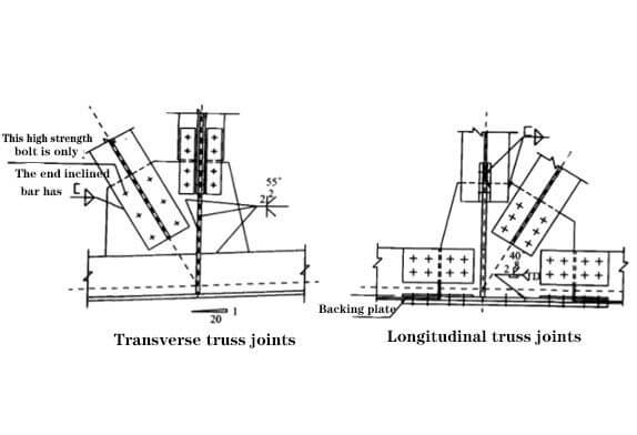
Figure 3 Truss joint construction
All steel structural components are manufactured in the factory, and the parts are transported to the site in Shenyang by railway transportation, with a single transport length of 12m. On the construction site, the 144m-span transverse trusses are pre-assembled on the ground one by one, and after passing the inspection, they are hoisted and installed in sections. The transverse trusses and peripheral trusses are assembled in sections with butt welds at high altitudes, and the length of the sections is generally about 18.24m. All the longitudinal trusses are assembled in pieces in the air with high-strength bolts. The installation process is from south to north (that is, along the longitudinal direction of the roof), first install the side trusses (each installation unit is 18m or 12m), and then assemble the segmented horizontal trusses into a whole at high altitude one by one. Then install the longitudinal trusses and support members at the corresponding parts.
Copyright © Xuzhou LF Engineering & Construction Co., Ltd. All Rights Reserved.

 +86-17751936871
 +86-516-8595-0258


