

+86 177 5193 6871
222, Block B, Diamond International, Guozhuang Road, Xuzhou, Jiangsu, China
Purlins are load-bearing and supporting members in a building envelope system; they form the skeleton of the structure and transfer loads to the roof trusses or beams, playing a crucial role in the overall integrity and stability of the roof structure. Specifically, purlins are horizontal roof beams perpendicular to the roof trusses or rafters, used to support the rafters or roofing materials. They are members subjected to lateral bending (typically two-way bending), and their primary function is to transfer roof loads to the roof trusses.
1. Types of Purlins
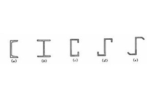
There are numerous types of purlins, which can be classified into various categories based on their cross-sectional shapes and materials. For example, classification by cross-sectional shape.
(1) Solid-web Type
Channel steel purlins, angle steel purlins, H-beam purlins, flanged channel-shaped cold-formed thin-walled steel, flanged Z-shaped cold-formed thin-walled steel, composite steel sections, etc.;
(2) Open-web type
Typically composed of angle steel (upper and lower chords) and gusset plates welded together; currently rarely used.
(3) Truss type
Divided into planar truss purlins and spatial truss purlins. These have clear load-bearing mechanisms and high overall stiffness, but are labor-intensive to manufacture and require a large amount of steel.
Currently, solid-web purlins are predominantly used in industrial buildings.
2. Emphasis on Purlin Load-Bearing Capacity Calculations
In some projects, the building envelope is installed solely based on relevant design manuals without undergoing structural analysis, resulting in insufficient load-bearing capacity and potentially causing wind uplift.
Purlins are typically calculated as two-way flexural members, with analysis focusing on their strength, stability, and deflection. Additionally, based on their load-bearing models, purlins can be classified as continuous or simply supported. Simply supported purlins are those where adjacent purlins are not connected at their supports; no bending moment is generated at the ends of simply supported purlins, and the maximum bending moment occurs at the midspan, making them statically determinate structures; Continuous purlins, on the other hand, are connected at the supports, forming a statically indeterminate structure. This allows for the adjustment of the mid-span bending moment, reducing the cross-sectional dimensions and resulting in a more economical design.
Purlin calculations may be performed in accordance with the provisions of Section 8.1 of the “Technical Specifications for Cold-Formed Thin-Walled Steel Structures” (GB50018-2002) and Section 9.1 of the “Technical Specifications for Steel Frame Lightweight Buildings” (GB51022-2015).
3. Common Damage and Defects
During construction, greater emphasis is often placed on the quality of the main structure, while the construction of the building envelope is sometimes neglected. This can lead to connection issues in the building envelope, increasing the risk of accidents such as wind uplift. Defects may arise in the installation of tie rods, purlin supports, or the connections between purlins.
The following lists some common purlin damage and defects, which can be summarized into three categories: design defects, construction defects, and insufficient maintenance.
(1) Corrosion, perforation, or fracture of purlins
(2) Missing or loose connecting bolts
(3) Welding of purlins directly to the flanges of purlin supports; missing connecting plates
(4) Missing or detached tie rods between purlins
(5) Self-tapping screws loosened or not installed
(6) Incorrect purlin dimensions (cross-sectional dimensions) / design errors
(7) Deformation or bending
(8) Connection plates at the purlin-to-purlin support joints are broken or deformed, or purlin support welds have cracked
(9) Broken connections at purlin ends
(10) Purlins cut or missing
(11) Connections between purlins and purlin supports, or between primary and secondary purlins, do not conform to the design
(12) Connections between purlins and purlin supports, or between primary and secondary purlins, consist solely of flange connections, with no measures in place to prevent end torsion or overturning
(13) Purlins installed in the wrong direction
The safety of purlins directly affects the safety of the building envelope system, which in turn directly impacts structural safety, operational safety, and personnel safety. During purlin design, due attention must be given to load requirements under extreme weather conditions and local climatic characteristics; materials must be selected rigorously, and joint designs optimized. During construction, quality control and supervision must be strengthened to ensure that on-site purlin materials, installation processes, and acceptance procedures comply with current national standards and construction drawings.
Copyright © Xuzhou LF Engineering & Construction Co., Ltd. All Rights Reserved.

 +86-17751936871
 +86-516-8595-0258


