

+86 177 5193 6871
222, Block B, Diamond International, Guozhuang Road, Xuzhou, Jiangsu, China
The connection structures of air-supported membrane structures shall ensure that connections are safe, rational, and aesthetically pleasing. When connection structures are eccentric, the impact on the cables and membrane material shall be taken into account. Membrane connections shall provide reliable watertightness and airtightness, and reliable measures shall be in place to prevent wear and tear of the membrane material.
The connection nodes of cables, anchor systems, and end connection details in air-supported membrane structures shall be selected in accordance with the provisions of the current industry standard “Technical Specifications for Cable Structures” (JGJ 257). Connectors shall reliably transmit forces and possess sufficient strength, stiffness, and durability; reliable anti-corrosion measures shall be taken for metal connectors.
1. Design of Connection Details Between Membrane Panels
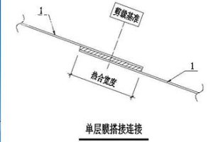
Based on the cutting design drawings, the membrane surface is cut into individual panels, referred to as membrane panels. The connection between membrane panels primarily employs heat-sealing, which may be implemented using either an overlap or butt joint method. The heat-sealing width for overlap or butt joints shall be determined experimentally based on the type of membrane material and the designed membrane surface tension, and shall simultaneously comply with the relevant provisions of the “Technical Specifications for Membrane Structures” CECS 158.
For lap joints, the upper membrane material shall overlap the lower membrane material.
For butt joints, treatment shall vary depending on the type of membrane material. Air-supported membrane structures typically use Type P membrane materials, which have a PVDF or PVF coating on the front surface and cannot be heat-sealed directly. Therefore, for Type P membrane materials in butt joints, the backing strip is placed beneath the main membrane material. In contrast, air-cushion membrane structures typically use Type E membrane materials, which have printed dots on the back surface and cannot be heat-sealed directly. Therefore, for Type E membrane materials in butt joints, the backing strip is placed above the main membrane material.
Air-supported membrane structures are typically single-layered; however, a double-layered construction may be used when thermal insulation is required. In this case, the outer and inner membranes are heat-sealed together at the panel joints. Air-cushion membrane structures are typically double-layered; when higher thermal insulation and heat resistance are required, a multi-layered construction may also be used. The outer and inner membranes—and, in multi-layered configurations, the intermediate membrane—are generally heat-sealed together along the perimeter of the air cushion.
2. Design of Membrane Unit Connection Structures
A membrane unit is a transport and installation unit formed by heat-sealing multiple membrane panels together and finishing the edges. In the design of air-cushion membrane structures, membrane units are not typically designed to connect directly to one another. However, for air-supported membrane structures with large areas, due to limitations in fabrication, transportation, and installation conditions, multiple membrane units fabricated in the factory are often connected directly at the construction site. Due to airtightness requirements, the connection between membrane units in air-supported membrane structures—whether single-layer or double-layer—typically employs sandwich panel connections.

3. Design of Connection Structures Between Membrane Units and Support Surfaces
Before inflation, a single membrane unit or a group of connected membrane units must be attached to the support surface. Given the unique nature of air-supported membrane structures, structural joints must not only meet load-bearing requirements but also ensure airtightness.
The connection between membrane units and the supporting surface in air-supported membrane structures typically employs one of the following three methods: pre-embedded aluminum channels, pre-embedded anchor bars, or pre-embedded structural steel.
For air-cushion membrane structures, the standard practice involves designing a secondary steel structure on the main structure, with the membrane units then connected to this secondary steel structure via aluminum profiles. Regarding the connection between air cushions, there are two common approaches: with or without a gutter.
4. Design of Cable Node Structures
For air-supported membrane structures with large spans, cable grids are typically used to reinforce the structure, control membrane tension, and limit structural deformation. Cable grid arrangements generally include diagonal cross-cable grids and longitudinal-transverse cable grids.
At the intersections of continuous cables, custom cable clamps can be used to connect them. When there are a large number of intersecting cables or the cable directions are complex, the cables can be segmented and connected using cable clamp plates.
The design of node structures for air-supported membrane structures is not limited to the methods described above. Designs should be flexible and tailored to actual conditions, but must always be safe, reliable, and aesthetically pleasing.
Copyright © Xuzhou LF Engineering & Construction Co., Ltd. All Rights Reserved.

 +86-17751936871
 +86-516-8595-0258


