

+86 177 5198 6706
222, Block B, Diamond International, Guozhuang Road, Xuzhou, Jiangsu, China
3.3 Rust Removal and Corrosion Protection for Steel Structures
Given that the steel structure is located in a coastal environment and exhibits numerous cracks caused by rust expansion, the primary objectives of the renovation are to repair and reinforce existing structural damage and to ensure durability for future use. Reinforcement and repair measures are applied to structural components based on the severity of the damage.
For structural components where rust expansion cracks have caused concrete loosening, spalling of the protective layer, and exposure/corrosion of reinforcing bars, severely corroded sections of the rebar must be replaced. Subsequently, cross-sectional repairs are performed using polymer mortar or grouting material.
As the extent of corrosion on the original dry coal shed was too vast for localized touch-up painting, chemical rust removal (using the JZ-CXFX rust-converting agent) was employed to treat the steel structure.
Following the rust removal treatment, an anti-rust film layer (polymerized aluminum-phosphorus-iron) formed on the surface of the steel structure. This non-conductive film effectively inhibits electrochemical reactions and prevents perforation corrosion. It remains stable within a temperature range of -40°C to 1,500°C and offers excellent fire resistance. The film bonds strongly to the steel substrate and paint, and is compatible with various common paints, coatings, and putties, thereby enhancing the quality of the paint finish and improving rust-prevention capabilities.
As the power plant is situated in a coastal region, all metal materials require high-quality surface treatment and painting to protect against corrosion caused by rainwater (especially acid rain), wastewater, sunlight, and the atmosphere, as well as to extend the equipment’s service life. The painting sequence is as follows: application of epoxy zinc-rich primer (selected structures) → inspection → application of epoxy micaceous iron oxide intermediate coat (selected structures) → inspection → application of polyurethane topcoat → inspection → application of thin-film fire-retardant coating → inspection. Before applying the topcoat to the steel structure, all dirt must be removed. Thorough rust removal and repair are mandatory for any rust or degradation accumulated during storage, as well as for weld zones from transport and assembly, and areas where the shop primer was damaged or defective due to heat treatment.
Use thinners or cleaning agents to remove residues such as grease, lubricating oil, solvents, weld slag, and spatter, as well as damaged paint coatings at weld sites or areas subjected to heat-based straightening; then, blow the surface dry with compressed air.
Remove weld slag and welding scale using wire brushes or steel wool. To protect the steel surface, wipe it clean immediately after cleaning; once inspection confirms full compliance with construction requirements, the first coat of anti-rust primer may be applied. The second topcoat layer may only be sprayed after thorough repair following the aforementioned processes and steps.
3.4 Bearing Replacement or Reinforcement Technology
The stiffener plates for all upper-chord bearings and some lower-chord bearings require replacement. The replacement steel plates are made of Q345B (or Q355B) grade steel; the specifications for both the steel plates and support steel pipes exceed those of the original materials, and the structural design increases the contact area between the stiffener plates, spherical nodes, and base plates.
When replacing bearings (specifically the bottom stiffener plates), calculations assume the removal of the bearing’s restraint at that location. Furthermore, structural safety under various states is calculated by grouping two bearings at symmetrical positions on the same side for each replacement operation. Given the inherent symmetry of the steel structure, calculations are performed using one side (axis) as the representative model.
Figure 5: Schematic of bearing reactions under static load
Based on the calculations, the bearing treatment is categorized into three zones.
Zone 1: Upper-chord axis bolted spherical node bearings. In this zone, the original stiffener plates and steel pipes can be cut away in a single operation and replaced with new ones.
Zone 2: Lower-chord axis welded spherical node bearings. Work in this section is carried out according to the steps shown in Figure 6.
-b.jpg)
(a) (b)
-d-e.jpg)
(c) (d)(e) Figure 6: Schematic of reinforcement steps for welded-ball supports: (a) Cut away the original stiffening plates and steel plates in the shaded area of the support; (b) Install new continuous stiffening plates (3/4 of the cruciform shape); (c) Cut away the remaining original stiffening plates and steel pipe in the shaded area; (d) Install new 1/4 stiffening plates; (e) Install new supporting steel pipe.
Zone 3: Welded-ball supports for top-chord and axial members. This section follows the steps for Zone 2; however, temporary reinforcement must be applied according to Figure 7 prior to processing, and the reinforcement measures must be removed upon completion.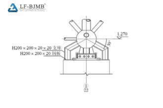
Figure 7: Schematic of temporary reinforcement for welded-ball supports.
3.5 Member replacement or reinforcement techniques
Principles for replacing or reinforcing steel structure members: Minimize the increase in the original structure’s total weight and avoid inducing secondary stresses; do not replace existing joints if their load-bearing capacity is sufficient, thereby avoiding excessive local dismantling that could cause the structure’s load-bearing capacity to exceed permissible limits during construction; for members connected by welded-ball joints at both ends (typically those bearing significant internal forces), apply reinforcement measures rather than dismantling them.
Since replacing a member requires dismantling the original member and potentially the bolted-ball joints at both ends, a simulation analysis must be performed before each dismantling step to verify structural safety; if unsafe, auxiliary support from a crane must be provided. Member replacement should be carried out in calm or light-wind conditions and, whenever possible, after the roof panels have been removed. If joints at both ends of a member must be dismantled, they should be removed separately—ensuring that no more than one joint is dismantled during any single construction period. Construction personnel must anchor their safety harnesses to adjacent joints and must not use the harnesses to drag components or tools. Key techniques for member replacement or reinforcement include the following:
(1) For members requiring replacement solely due to corrosion, substitute them with members of the same specifications and material.
(2) For overstressed members, first consider changing the material to Q355B while keeping the specifications unchanged; only consider increasing the member specifications if the material change fails to meet requirements.
(3) When the strength of high-strength bolts is insufficient to meet joint load-bearing requirements, increase the size of the high-strength bolts… …bolt specifications, and replace the corresponding bolted spherical joints.
(4) If the load-bearing capacity of the sleeve is insufficient, replace the sleeve material with No. 45 steel or Q355B steel.
(5) If the contact surface between the bolted sphere and the sleeve fails to meet load-bearing requirements, replace the bolted sphere; during replacement, aim to keep the sphere diameter unchanged while increasing only the size of the flattened area at the corresponding bolt hole. Reinforcement measures for members connected to welded spheres on both sides are shown in Figure 8; specific cross-sections are determined through calculation.
.jpg)
(a)
.jpg)
(b)
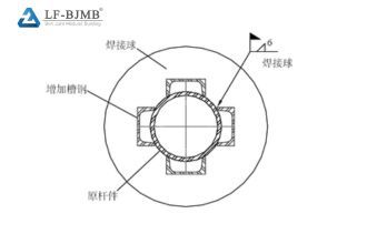
(c)
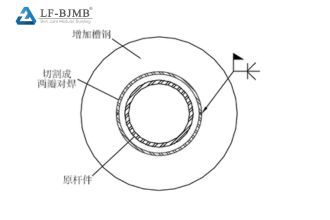
(d) Figure 8: Schematic of reinforcement for members connected to welded spheres (a) Scheme 1; (b) Scheme 2; (c) Scheme 3; (d) Scheme 4
4 Conclusion
Through in-depth research on reinforcement techniques for a 30-year-old bolted-sphere steel coal shed, various reinforcement schemes have been proposed. These schemes encompass key technologies such as member replacement, support reinforcement, and replacement of color-coated steel roofing, aiming to enhance the structural stability and durability of the coal shed to meet long-term operational needs.
ANSYS software was used to analyze wind loads during the reinforcement of the dry coal shed. The results indicate that, considering only wind pressure, the maximum stress in the members ranges from –173 to 145 N/mm², demonstrating an ample safety margin. The structure remained in a safe state throughout the reinforcement process.
For the 30-year-old double-layer reticulated shell structure (diagonal square-pyramid grid type), a reinforcement scheme was implemented involving support replacement, member reinforcement and repair, replacement or reinforcement of all overstressed members, local concrete foundation reinforcement, and assessment of the impact of adding a roof monitor and catwalks on the original steel structure, alongside anti-corrosion treatment for replaced components, equipment, and piping; this approach yielded excellent results.
The success of the dry coal shed reinforcement project provides practical engineering solutions for the specific details involved in reinforcing 30-year-old bolted-sphere steel structures. Conducting reinforcement analysis on such long-service-life steel structures avoids the waste associated with outright demolition and offers valuable experience for the maintenance and renovation of similar structures.
Copyright © Xuzhou LF Engineering & Construction Co., Ltd. All Rights Reserved.


 +86 177 5198 6706
 +86-516-8595-0258


